Download
1 / 78
820 likes | 1.06k Vues
Learn about the transmission of motion and power using belt drives in mechanical systems. Explore different types of belt drives, materials used, and their applications in industrial machinery.

E N D
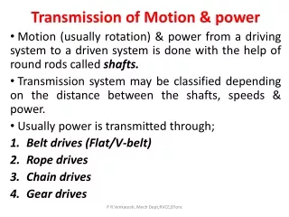
Transmission of Motion & power Motion (usually rotation) & power from a driving system to a driven system is done with the help of round rods called shafts. Transmission system may be classified depending on the distance between the shafts, speeds & power. Usually power is transmitted through; Belt drives (Flat/V-belt) Rope drives Chain drives Gear drives P R Venkatesh, Mech Dept,RVCE,B'lore
Belt Drives Belt drives are called flexible machine elements. Flexible machine elements are used for a large number of industrial applications, some of them are as follows: 1. Used in conveying systems: Transportation of coal, mineral ores etc. over a long distance. 2. Used for transmission of power. Mainly used for running of various industrial appliances using prime movers like electric motors, I.C. Engine etc. P R Venkatesh, Mech Dept,RVCE,B'lore
Simple & Compound Belt Drives The lower side of the belt will have more tension & is called the Tight side. The upper side of the belt will have less tension & is called the Slack side. Belt Materials: Leather, rubber, canvas, balata (rubber with cotton) P R Venkatesh, Mech Dept,RVCE,B'lore
Typical belt drives • Two types of belt drives, an open belt drive, and a crossed belt drive are shown. • In both the drives, a belt is wrapped around the pulleys. • Let us consider the larger pulley to be the driving pulley. This pulley will transmit motion to the belt and the motion of the belt in turn will give a rotation to the smaller driven pulley. • In open belt drive system the rotation of both the pulleys is in the same direction, whereas, for crossed belt drive system, opposite direction of rotation is observed. P R Venkatesh, Mech Dept,RVCE,B'lore
Jockey pulleys are used to get proper arc of contact. It increases the angle of wrap and there by reduce the belt tensions required for a given power. Normally the idler pulley is located near to the smaller diameter pulley. • It is non reversible. • The bending stress developed in the belt reduces the belt drive. • Requires endless belt. P R Venkatesh, Mech Dept,RVCE,B'lore
Stepped Cone Pulley • A stepped cone pulley is used when the speed of the driven shaft it is to be changed very frequently as in case of machine tools such as lathe, drilling machine, etc. • A stepped cone pulley is an integral casting having 3 or more steps. • By shifting the belt from one pair of pulleys to another, the same belt will transmit different speeds. P R Venkatesh, Mech Dept,RVCE,B'lore
Stepped Cone pulley P R Venkatesh, Mech Dept,RVCE,B'lore
Fast & Loose Pulley • Fast & loose pulley is used when it is required to stop the driven pulley without stopping the driving pulley. • A fast pulley will be keyed to the driven shaft while a loose pulley fitted with a brass bush is freely rotating on the shaft. • The driving pulley will be wider and the belt may be shifted to the loose pulley whenever the driven shaft is required to be brought to rest. P R Venkatesh, Mech Dept,RVCE,B'lore
Fast & Loose pulley P R Venkatesh, Mech Dept,RVCE,B'lore
LENGTH OF BELT FOR OPEN BELT DRIVE P R Venkatesh, Mech Dept,RVCE,B'lore
LENGTH OF BELT FOR OPEN BELT DRIVE P R Venkatesh, Mech Dept,RVCE,B'lore
LENGTH OF BELT FOR CROSSED BELT DRIVE P R Venkatesh, Mech Dept,RVCE,B'lore
RATIO OF TENSIONS IN FLAT BELT DRIVE P R Venkatesh, Mech Dept,RVCE,B'lore
Slip in belt drives Slip in belt drives is the relative motion between the belt & pulley due to lack of frictional grip between them. This results in the forward motion of the driving pulley without carrying the belt with it and the forward motion of the belt without carrying the driven pulley with it. Slip is expressed as a percentage and it results in reduction in velocity ratio transmitted by the belt. P R Venkatesh, Mech Dept,RVCE,B'lore
Creep in belt drives Creep in belt drives is the relative motion between the belt & pulley due to elongation and contraction of the belt as it moves from tight side to slack side. Creep occurs when the material of the belt is not perfectly elastic resulting in slightly more elongation than contraction of the belt. Creep also results in reduction in velocity ratio and power transmitted by the belt. P R Venkatesh, Mech Dept,RVCE,B'lore
INITIAL TENSION IN BELT DRIVES • The tension provided in the belt while mounting it on the pulleys when stationary is known as ‘Initial Tension’ represented by To. • When the pulleys start rotating, the tension on the tight side increases to T1 & that on the slack side decreases to T2 due to expansion & contraction of the belt. P R Venkatesh, Mech Dept,RVCE,B'lore
Advantages of flat belt drives Easy, flexible equipment design, as tolerances are not important. Isolation from shock and vibration between driver and driven system. Belt drives require no lubrication. Maintenance is relatively convenient Very quiet compared to chain drives, and direct spur gear drives. Disadvantages of flat belt drives Not suitable for short center distances. Exact velocity ratio can not be maintained. Large power can not be transmitted effectively. P R Venkatesh, Mech Dept,RVCE,B'lore
V-Belts V-belts are used in high power transmission due to wedging action between the trapezoidal belt & the grooves on the pulley. They are moulded as endless loops from rubber reinforced with fibrous material. They run V-grooves on the pulleys and multiple belts can be used for high power transmission upto 150 KW. P R Venkatesh, Mech Dept,RVCE,B'lore
V-Belts Cross section of V-Belts P R Venkatesh, Mech Dept,RVCE,B'lore
Problem 1 In a belt drive, the velocity ratio is 3. The driving pulley runs at 400 rpm. The diameter of the driven pulley is 30 cm. Find the speed of the driven pulley and the diameter of the driving pulley. P R Venkatesh, Mech Dept,RVCE,B'lore
Problem 1 P R Venkatesh, Mech Dept,RVCE,B'lore
Problem 2 The sum of diameters of two pulleys is 1000 mm and the pulleys are connected by a belt. If the pulleys rotate at 600 rpm & 1800 rpm, determine the size of each pulley. P R Venkatesh, Mech Dept,RVCE,B'lore
Problem 2 P R Venkatesh, Mech Dept,RVCE,B'lore
Problem 3 An engine shaft running at 200 rpm is required to drive a generator at 300 rpm by means of a flat belt drive. Pulley on the driving shaft has 500 mm diameter. Determine the diameter of the pulley on the generator shaft if the belt thickness is 8 mm & slip is 4%. P R Venkatesh, Mech Dept,RVCE,B'lore
Problem 3 P R Venkatesh, Mech Dept,RVCE,B'lore
Problem 4 Power is to be transmitted from a pulley of 600 mm diameter to another pulley of 300 mm diameter by means of a belt. The center distance between the pulleys is 3m. Determine the length of the belt required if the pulleys are connected by • Open belt • Crossed belt P R Venkatesh, Mech Dept,RVCE,B'lore
Problem 5 A flat open belt drive consists of pulleys of diameters 1000 mm & 500 mm with a center distance of 1500 mm. The coefficient of friction between the pulley and the belt is 0.3. When the maximum tension in the belt is 700 N, find the power transmitted by the belt when the smaller pulley rotates at 400 rpm. P R Venkatesh, Mech Dept,RVCE,B'lore
Problem 5 P R Venkatesh, Mech Dept,RVCE,B'lore
Problem 5 P R Venkatesh, Mech Dept,RVCE,B'lore
Problem 6 In a belt drive, the angle of lap on the driven pulley is 1600 and the coefficient of friction between the pulley & the belt material is 0.28. If the width of the belt is 200 mm and the maximum tension in the belt is not to exceed 5 N per mm width, find the initial tension in the belt. P R Venkatesh, Mech Dept,RVCE,B'lore
CHAIN DRIVES • Chain drives consist of an endless series of connected links that mesh with toothed wheels called sprockets. • These sprockets in turn, are keyed to the driving and driven shafts. • Chain drives are positive drives (No slip & creep) and can operate for short center distances. • They are used for transmission of motion & power in bicycles, motor vehicles, agricultural machinery, etc. • Velocity ratio in chain drives is given by P R Venkatesh, Mech Dept,RVCE,B'lore
Roller Chains P R Venkatesh, Mech Dept,RVCE,B'lore
Inverted tooth Chains Or Silent Chains (So named due to quiet operation even under heavy loads) P R Venkatesh, Mech Dept,RVCE,B'lore
Gears Gears are toothed wheels used to transmit power from one shaft to another when a constant velocity ratio is desired and the distance between shafts is relatively small. Gears are classified as follows: (i) According to relative position of shaft axes: Parallel axes : Spur gear, helical gear Intersecting axes : Bevel gears Non parallel, Non intersecting: Worm gears (ii) According to peripheral velocity (v) of gears: V< 3 m/sec: Low velocity gears 3<V< 15 m/sec: Medium velocity gears V>15 m/sec: High velocity gears P R Venkatesh, Mech Dept,RVCE,B'lore
(iii) According to type of gearing: Gears mesh externally & hence rotate in opposite directions : External gearing Gears mesh internally & hence rotate in same directions: Internal gearing (iv) According to position of the teeth on gear surface: Straight teeth: Spur gears Inclined teeth: Helical gears Skewed (curved) teeth: Spiral gear P R Venkatesh, Mech Dept,RVCE,B'lore
Spur Gears • This is the simplest form of gears for transmitting power between two parallel shafts. The teeth are straight & parallel to the axis. • Spur gears impose only radial loads on bearings. • Because of the instantaneous line contact during meshing, the drive will be noisy. • Spur gear drive is widely used in machine tools, automobile gear boxes, etc. P R Venkatesh, Mech Dept,RVCE,B'lore
Spur gear pair (External & Internal) Pitch cylinders with pure rolling friction Spur gear animation P R Venkatesh, Mech Dept,RVCE,B'lore
Helical Gears • Helical gears are used to transmit power between parallel shafts. • In these gears, the teeth are inclined to the axis of the shaft at an angle known as Helix angle (150 to 450). • Helical gears are preferred to spur gears as their operation is quiet due to progressive engagement of teeth. • The disadvantage of helical gears is it produces an axial thrust. Hence double helical gears (herringbone gears) are used. P R Venkatesh, Mech Dept,RVCE,B'lore