Download
1 / 18
200 likes | 353 Vues
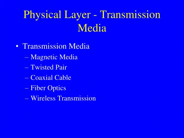
Wireless Transmission Fundamentals (Physical Layer). Professor Honggang Wang Email: hwang1@umassd.edu. Electromagnetic Spectrum. Wireless communication uses 100 kHz to 60 GHz. Network. Network. The Layered R eference Model. Application. Application. Transport. Transport. Network.

E N D
Wireless Transmission Fundamentals (Physical Layer) Professor Honggang Wang Email: hwang1@umassd.edu
Electromagnetic Spectrum • Wireless communication uses 100 kHz to 60 GHz
Network Network The Layered Reference Model Application Application Transport Transport Network Network Data Link Data Link Data Link Data Link Physical Physical Physical Physical Medium Radio Often we need to implement a function across multiple layers.
Outline • RF introduction • Antennas and signal propagation • How do antennas work • Propagation properties of RF signals • Modulation and channel capacity
What is Antenna • Conductor that carries an electrical signal and radiates an RF signal. • The RF signal “is a copy of” the electrical signal in the conductor • Also the inverse process: RF signals are “captured” by the antenna and create an electrical signal in the conductor. • This signal can be interpreted (i.e. decoded) • Efficiency of the antenna depends on its size, relative to the wavelength of the signal. • e.g. half a wavelength
Types of Antennas • Antenna is a point source that radiates with the same power level in all directions – omni-directional or isotropic • An antenna that transmits equally in all directions (isotropic) • Shape of the conductor tends to create a specific radiation pattern • Common shape is a straight conductor • Shaper antennas can be used to direct the energy in a certain direction • Well-know case: a parabolic antenna A parabolic antenna
Signal Propagation Ranges • Transmission range • communication possible • low error rate • Detection range • detection of the signal possible • no communication possible • Interference range • signal may not be detected • signal adds to the background noise sender transmission distance detection interference
Signal propagation • Propagation in free space always like light (straight line) • Receiving power proportional to 1/d² in vacuum – much more in real environments(d = distance between sender and receiver) • Receiving power additionally influenced by fading (frequency dependent) • Shadowing • Reflection at large obstacles • Refraction depending on the density of a medium • Scattering at small obstacles • Diffraction at edges refraction shadowing reflection scattering diffraction
Propagation Degrades RF Signal • Attenuation in free space • Signal gets weaker as it travels over longer distance • Free space loss- Signal spreads out • Refraction and absorption in the atmosphere • Obstacle can weaken signal through absorption or reflection. • Part of the signal is re-directed. • Multiple path effects • Multiple copies of the signal interfere with each other • Mobility • Moving receiver causes another form of self interference • Node moves ½ wavelength cause big change in signal strength (dB) Signal Received path loss Power location log (distance)
Decibels • Attenuation = 10 Log10 (Pin/Pout) decibel • Attenuation = 20 Log10 (Vin/Vout) decibel • Example 1: Pin = 10 mW, Pout=5 mW • Attenuation = 10 log 10 (10/5) = 10 log 10 2 = 3 dB • Example 2: Pin = 100mW, Pout=1 mW • Attenuation = 10 log 10 (100/1) = 10 log 10 100 = 20 dB
Shadowing • Signal strength loss after passing through obstacles • Some sample numbers i.e. reduces to ¼ of signal10 log(1/4) = -6.02
Multipath • Signal can take many different paths between sender and receiver due to reflection, scattering, diffraction
Multipath propagation • Signal can take many different paths between sender and receiver due to reflection, scattering, diffraction • Time dispersion: signal is dispersed over time • interference with “neighbor” symbols, Inter Symbol Interference (ISI) • The signal reaches a receiver directly and phase shifted • distorted signal depending on the phases of the different parts multipath pulses LOS pulses signal at receiver signal at sender
Multipath Effects • Receiver receives multiple copies of the signal, each following a different path • Copies can either strengthen or weaken each other • Depends on whether they are in our out of phase • Small changes in location can result in big changes in signal strength • Larger difference in path length can cause intersymbol interference (ISI) • More significant for higher bit rates (shorter bit times)
Free-Space Isotropic Signal Propagation • In free space, receiving power proportional to 1/d² (d = distance between transmitter and receiver) • Suppose transmitted signal is x,received signal y = h x, where h is proportional to 1/d² • Loss depends on the frequency: Higher loss with higher frequency • Loss increase quickly with distance (d^2) • Pr: received power • Pt: transmitted power • Gr, Gt: receiver and transmitter antenna gain • (=c/f): wave length Sometime we write path loss in log scale:Lp = 10 log(Pt) – 10log(Pr)
Effects of mobility • Channel characteristics change over time and location • signal paths change • different delay variations of different signal parts • different phases of signal parts • quick changes in the power received (short term fading) • Fading: time variation of the received signal strength caused by changes in the transmission medium or paths. • Rain, moving objects, moving sender/receiver, … • Additional changes in • distance to sender • obstacles further away • slow changes in the averagepower received (long term fading) long term fading power short term fading t
Outline • RF introduction • Antennas and signal propagation • How do antennas work • Propagation properties of RF signals • Modulation and channel capacity
Q/A ???