Download
1 / 22
220 likes | 243 Vues
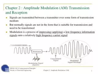
This chapter explores Amplitude Modulation (AM) principles, including Double Sideband Suppressed Carrier (DSSC) and Single Sideband Signals (SSB). It covers bandpass signaling, modulation efficiency, envelope detection, and carrier recovery methods for different modulation types. Examples illustrate message signal modulation scenarios, normalized power calculations, and power spectrum analysis. The content delves into the intricacies of AM signal power distribution, modulation efficiency, and the generation of Single Sideband (SSB) signals.

E N D
Chapter 5 • AM, FM, and Digital Modulated Systems • Amplitude Modulation (AM) • Double Sideband Suppressed carrier (DSSC) • Single sideband signals (SSB) Hüseyin Bilgekul & Erhan Ince Eeng360 Communication Systems I Department of Electrical and Electronic Engineering Eastern Mediterranean University
Bandpass Signaling Review Where Where • The modulated bandpass signal can be described by Modulation Mapping function:Convert m(t) →g(t) Ref :Table4-1 • The voltage spectrum of the bandpass signal is • The PSD of the bandpass signal is
Amplitude Modulation • The Complex Envelope of an AM signal is given by Ac indicates the power level of AM and m(t) is the Modulating Signal • Representation of an AM signal is given by • Ac[1+m(t)] In-phase component x(t) • If m(t) has a peak positive values of +1 and a peak negative value of -1 AM signal 100% modulated • Envelope detection can be used if % modulation is less than 100%.
Amplitude Modulation An Example of a message signal m(t) Waveform for Amplitude modulation of the message signal m(t)
Amplitude Modulation B An Example of message energy spectral density. Carrier component together with the message 2B Energy spectrum of the AM modulated message signal.
AM – Percentage Modulation • Definition: The percentage of positive modulation on an AM signal is • The percentage of negative modulation on an AM signal is • The percentage of overall modulation is If m(t) has a peak positive values of +1 and a peak negative value of -1 AM signal 100% modulated
AM Signal Waveform % Positive modulation= 50% % Negative modulation =50% Overall Modulation = 50% Amax = 1.5Ac Amin = 0.5 Ac
AM – Percentage Modulation Under modulated (<100%) 100% modulated Over Modulated (>100%) Envelope Detector Can be used Envelope Detector Gives Distorted signal
AM – Normalized Average Power The normalized average power of the AM signal is If the modulation contains no dc level, then The normalized power of the AM signal is Discrete Carrier Power Sideband power
AM – Modulation Efficiency • Definition : The Modulation Efficiency is the percentage of the total power of the modulated signal that conveys information. Only “Sideband Components” – Convey information Modulation Efficiency: Highest efficiency for a 100% AM signal : 50% - square wave modulation Normalized Peak Envelope Power (PEP)of the AM signal: Voltage Spectrum of the AM signal: Unmodulated Carrier Spectral Component Translated Message Signal
The peak envelope power (PEP) is Example 5-1. Power of an AM signal Suppose that a 5000-W AM transmitter is connected to a 50 ohm load; Without Modulation Then the constant Acis given by If the transmitter is then 100% modulated by a 1000-Hz test tone , the total (carrier + sideband) average power will be The peak voltage (100% modulation) is (2)(707) = 1414 V across the 50 ohm load. The modulation efficiency would be 33% since < m2(t) >=1/2
Carrier Power Sideband power Spectrum Modulation Efficiency Double Side Band Suppressed Carrier (DSBSC) • Power in a AM signal is given by • DSBSC is obtained by eliminating carrier component • If m(t) is assumed to have a zero DC level, then Power • Disadvantages of DSBSC: • Less information about the carrier will be delivered to the receiver. • Needs a coherent carrier detector at receiver
DSBSC Modulation B An Example of message energy spectral density. No Extra Carrier component 2B Energy spectrum of the DSBSC modulated message signal.
Carrier Recovery for DSBSC Demodulation • Coherent reference for product detection of DSBSC can not be obtained by the use of ordinary PLL because there are no spectral line components at fc.
Carrier Recovery for DSBSC Demodulation • A squaring loop can also be used to obtain coherent reference carrier for product detection of DSBSC. A frequency divider is needed to bring the double carrier frequency to fc.
LSSB USSB Single Sideband (SSB) Modulation • An upper single sideband (USSB) signal has a zero-valued spectrum for • A lower single sideband (LSSB) signal has a zero-valued spectrum for • SSB-AM – popular method ~ BW is same as that of the modulating signal. Note: Normally SSB refers to SSB-AM type of signal
–Hilbert transform of m(t) Where and H(f) j f -j Single Sideband Signal • Theorem :A SSB signal has Complex Envelopeand bandpass form as: Upper sign (-) USSB Lower sign (+) LSSB Hilbert Transform corresponds to a -900phase shift
Using Recall from Chapter 4 Single Sideband Signal Proof: Fourier transform of the complex envelope Upper sign USSB Lower sign LSSB Upper sign USSB If lower signs were used LSSB signal would have been obtained
SSB - Power The normalized average power of the SSB signal Hilbert transform does not change power. SSB signal power is: Power of the modulating signal Power gain factor The normalized peak envelope (PEP) power is:
Generation of SSB SSB signals have bothAM and PM. The complex envelope of SSB: For the AM component, For the PM component, Advantages of SSB • Superior detected signal-to-noise ratio compared to that of AM • SSB has one-half the bandwidth of AM or DSB-SC signals
Generation of SSB • SSB Can be generated using two techniques • Phasing method • Filter Method • Phasing method This method is a special modulation type of IQ canonical form of Generalized transmitters discussed in Chapter 4 ( Fig 4.28)