Configuration of L2-Muon Cells and Chambers for Enhanced Spatial Orientation
This document outlines the spatial orientation and settings of the L2-Muon detectors as configured for Run-I and the adjustments made for chambers 115, 135, 116, and 136, which have undergone (x,p) rotations. It provides a detailed overview of the positioning and staggering of the cells within the system, including the placement of toroids and calorimeters in relation to east and west chambers. The mapping of the readout boards and the scintillator coverage for central PDTs are highlighted to ensure optimal performance in detecting muons.

Configuration of L2-Muon Cells and Chambers for Enhanced Spatial Orientation
E N D
Presentation Transcript
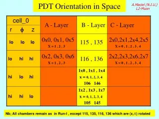
cell_0 r fz A - Layer B - Layer C - Layer lo lo lo 0X0, 0X1, 0X5 X = 1 , 2 , 3 115 , 135 2X0,2X1,2X4,2X5 X = 0 , 1 , 2 , 3 , 4 lo hi hi 0X2, 0X3, 0X6 X = 1 , 2 , 3 116 , 136 2X2,2X3,2X6,2X7 X = 0 , 1 , 2 , 3 , 4 hi lo hi 1x0 , 1x1 , 1x4 x = 0, 1, 2, 3, 4 106 146 hi hi lo 1x2 , 1x3 , 1x7 x = 0, 1, 2, 3, 4 105 145 A.Maciel (N.I.U.) L2-Muon PDT Orientation in Space Nb; All chambers remain as in Run-I , except 115, 135, 116, 136 which are (x,p) rotated
A.Maciel (N.I.U.) L2-Muon Cell 0 Position for East Chambers as Seen from East ( Assembly Bay View ) 241 221 201 141 121 101 Toroid 031 021 011 Cell Stagger (C) 0 Cell Stagger (A) 0 Calorimeter North South (B) 0 036 026 016 Toroid E-away 146 136 116 106 E-away 246 206 Note chambers 116 and 136 rotated (x,p) w.r.to run-1 West seen from West reproduces same cell-0 pattern 146 116 E-away All others E-near
Central PDT’s Local fOrientation Map A.Maciel (N.I.U.) L2-Muon Electronics Readout Boards Toroids EAST WEST Calorimeter Bottom B-Layer exceptions Bottom B-Layer exceptions 115 135 116 136 105 145 106 146
Scintillator Coverage for Central PDT’s Z Central C-layer PDT Central A-layer PDT C D E F A B C D E A B C D E 8 9 A B 5 6 7 8 9 5 6 7 8 9 4 5 6 7 0 1 2 3 4 0 1 2 3 4 0 1 2 3 φ For Aφ counters, each SFE holds a half octant