Download
1 / 10
100 likes | 197 Vues
PDT Low Voltage P.S. 94 LVPS Packages mounted 4’-25’ from the front-end electronics. 4 modules per package. +5V& -5V “Digital”, +5V & -5V “Analog” 18 A 1A 18A 18Amps. LVPS Connections. LVPS Testing.

E N D
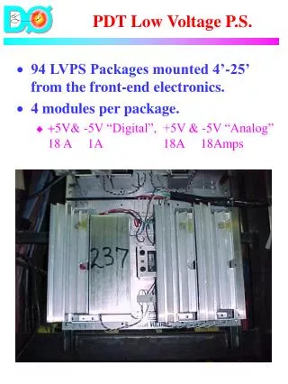
PDT Low Voltage P.S. • 94 LVPS Packages mounted 4’-25’ from the front-end electronics. • 4 modules per package. • +5V& -5V “Digital”, +5V & -5V “Analog” 18 A 1A 18A 18Amps
LVPS Testing • Procedure(on d0mino)/RunII/home/room2/diehl/muonup/1999/lvps_test.txt • Disconnect front-end electronics from Renwa card • Check wires connections at both ends • Measure load internal resistance • Power up with a simulated load & adjust voltages to read proper voltage output • Reconnect electronics with FEB cards • Typical malfunctions (Alonso G.) • Loose wires • 60% • Wrong connections in wiring-esp. sense leads • 40% • Bad power supplies • 9 of 88 Power supplies • Bad soldering on the lead wires of the power supplies • 5 of 88 Power supplies
LVPS Status • Total: 94 Supplies • Installed: 90 (not yet: 105, 106, 145,146) • Completely Connected: ~78 (many in the A-layer don’t have a power trunk yet). • Operating: ~66 (Bottom B & C-layer not operating, incomplete electronics) • Power Supply Operation: • A couple modules have been replaced. In retrospect, the problems have likely been related to the modules A.C. connections, rather than to component failure. • Plan to Finish: • Install 4 remaining LVPS after EF’s are closed. • Victor M. has material to make long power trunks. Install in 2-wk shutdown.
PDT High Voltage • 94 PDT’s each have two H.V. inputs. • Operating Voltage • On mini-pdt (small length) • Wire: 4.65 kv Pad: 2.3 kv • On the real thing (not finalized?) • Wire: 4.7 kv Pad: 2.3 kv • Status of MCH2: • 2 Crates, 47 pods • All pods installed • All pods have been operated • Pods not tested for extended periods
PDT Business End • Service Cards • 3 Types • Recently purchased spares for A-layer • Now have sufficient spares of all kinds.
HV On Detector • POD to PDT Map • Sensible division of PDT’s to Pods • Averages 2 PDT’s per pod • Large A-layer PDT’s each have own pods • Bottom A-layer PDT’s ganged 3/pod • Quiet Bottom C-layer PDT’s ganged 4/pod • See file http://wwwd0.fnal.gov/hardware/upgrade/muon_upgrade/Image3.gif • Tested recently to make sure pod # matched the appropriate Reynolds output. • 6 PDT’s (B&C-layer top east, octant 1) have been operated on a couple of gasses since last summer.
HV On Detector • 70 (-3) PDT’s are connected to HV pods. • 3 PDT’s (243, 135, 141) are disconnected because of broken wires. • 67 PDT’s OK at 200V on wire and pad • 36 PDT’s have been brought up to full voltage. • Plan: • Upon gas flow: bring the PDT’s to full voltage. Measure/track beam-off currents. • Finish cable installation in the 2 week shutdown • Repair/jumper cells with broken wires on access
Summary • LVPS • 90/94ths installed • 66/94ths operating • No evidence of LVPS pod failure • Finish during the 2 wk shutdown. • High Voltage System • Infrastructure MCH2 complete • 67/94ths ready to be brought up to full voltage once gas is flowing. • Finish during the 2 wk shutdown.