Download
1 / 40
540 likes | 1.12k Vues
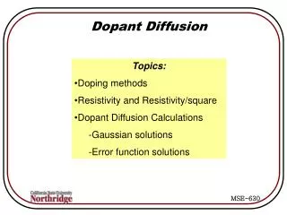
Dopant and Self-Diffusion in Silicon and Silicon Germanium. Eugene Haller, Hughes Silvestri, and Chris Liao MS&E, UCB and LBNL FLCC Tutorial 4/18/05. Outline. Motivation Background Fick’s Laws Diffusion Mechanisms Experimental Techniques for Solid State Diffusion

E N D
Dopant and Self-Diffusion in Silicon and Silicon Germanium Eugene Haller, Hughes Silvestri, and Chris Liao MS&E, UCB and LBNL FLCC Tutorial 4/18/05
Outline • Motivation • Background • Fick’s Laws • Diffusion Mechanisms • Experimental Techniques for Solid State Diffusion • Diffusion of Si in Stable Isotope Structures • Future Work: Diffusion of SiGe in Stable Isotope Structures • Conclusions FLCC Tutorial
Motivation • Why diffusion is important for feature level control of device processing • Nanometer size feature control: - any extraneous diffusion of dopant atoms may result in device performance degradation • Drain extension Xj < 10 nm by 2008* • Extension lateral abruptness < 3 nm/decade by 2008* • Accurate models of diffusion are required for dimensional control on the nanometer scale *International Technology Roadmap for Semiconductors, 2004 Update FLCC Tutorial
Semiconductor Technology Roadmap (International Technology Roadmap for Semiconductors, 2004 Update) FLCC Tutorial
Planar Bulk-Si Structure Thin-Body Structure scaling to Lg < 20nm MOSFET Scaling Si1-xGex in the S/D regions will be needed for thin-body PMOSFETs in order to • enhance mobility via strain • lower parasitic resistance • S/D series resistance • contact resistance Si and Ge interdiffusion, as well as B diffusion in Si1-xGex and Si must be well understood and characterized Courtesy of Pankaj Kalra and Prof. Tsu-Jae King FLCC Tutorial
Jin Jout dx Example: Vacancy Mechanism Fick’s Laws (1855) Fick’s 1st Law: Flux of atoms 2nd Law Diffusion equation does not take into account interactions with defects! Jout Jin -RS +GS FLCC Tutorial
Analytical Solutions to Fick’s Equations D = constant - Finite source of diffusing species: Solution: Gaussian - Infinite source of diffusing species: Solution: Complementary error function FLCC Tutorial
Solutions to Fick’s Equations (cont.) D = f (C) Diffusion coefficient as a function of concentration Concentration dependence can generate various profile shapes and penetration depths FLCC Tutorial
Solid-State Diffusion Profiles Experimentally determined profiles can be much more complicated - no analytical solution Kennel, H.W.; Cea, S.M.; Lilak, A.D.; Keys, P.H.; Giles, M.D.; Hwang, J.; Sandford, J.S.; Corcoran, S.; Electron Devices Meeting, 2002. IEDM '02, 8-11 Dec. 2002 B implant and anneal in Si with and without Ge implant FLCC Tutorial
Direct Diffusion Mechanisms in Crystalline Solids (no native defects required) Pure interstitial Elements in Si: Li, H, 3d transition metals Direct exchange No experimental evidence High activation energy → unlikely FLCC Tutorial
Vacancy-assisted Diffusion Mechanisms (native defects required) Vacancy mechanism (Sb in Si) Dissociative mechanism (Cu in Ge) FLCC Tutorial
Interstitial-assisted Diffusion Mechanisms (native defects required) Interstitialcy mechanism (P in Si) Kick-out mechanism (B in Si) FLCC Tutorial
Why are Diffusion Mechanisms Important? • Device processing can create non-equilibrium native defect concentrations • Implantation: excess interstitials • Oxidation: excess interstitials • Nitridation: excess vacancies • High doping: Fermi level shift FLCC Tutorial
Oxidation Effects on Diffusion • Oxidation of Si surface causes injection of interstitials into Si bulk • Increase in interstitial concentration causes enhanced diffusion of B, As, but retarded Sb diffusion • Nitridation (vacancy injection) causes retarded B, P diffusion, enhanced Sb diffusion Oxidation during device processing can lead to non-equilibrium diffusion (Fahey, et al., Rev. Mod. Phys. 61 289 (1989).) FLCC Tutorial
Implantation Effects on Diffusion Transient Enhanced Diffusion (TED) -Eaglesham, et al., Appl. Phys. Lett.65(18) 2305 (1994). • Implantation damage generates excess interstitials • Enhance the diffusion of dopants diffusing via interstitially-assisted mechanisms • Transient effect - defect concentrations return to equilibrium values • TED can be reduced by implantation into an amorphous layer or by carbon incorporation into Si surface layer • Substitutional carbon acts as an interstitial sink • Stolk, et al., Appl. Phys. Lett.66 1371 (1995) FLCC Tutorial
Ec 0.11 eV V--/- 0.57 eV V-/o 0.35 eV Io/+ 0.13 eV V+/++ 0.05 eV Vo/+ Ev Doping Effects on Diffusion Heavily doped semiconductors - extrinsic at diffusion temperatures • Fermi level moves from mid-gap to near conduction (n-type) or valence (p-type) band. • Fermi level shift changes the formation enthalpy, HF, of the charged native defect • Increase of CI,V affects Si self-diffusion and dopant diffusion V states (review by Watkins, 1986) FLCC Tutorial
Doping Effects on Diffusion The change in native defect concentration with Fermi level position causes an increase in the self- and dopant diffusion coefficients FLCC Tutorial
Experimental Techniques for Diffusion Creation of the Source • Diffusion from surface • Ion implantation • Sputter deposition • Buried layer (grown by MBE) Annealing Analysis of the Profile • Radioactivity (sectioning) • SIMS • Neutron Activation Analysis • Spreading resistance • Electro-Chemical C/Voltage Modeling of the Profile • Analytical fit • Coupled differential eq. FLCC Tutorial
Primary Experimental Approaches • Radiotracer Diffusion • Implantation or diffusion from surface • Mechanical sectioning • Radioactivity analysis • Stable Isotope Multilayers – new approach • Diffusion from buried enriched isotope layer • Secondary Ion Mass Spectrometry (SIMS) • Dopant and self-diffusion FLCC Tutorial
Radiotracer Diffusion • Diffusion using radiotracers was first technique available to measure self-diffusion • Limited by existence of radioactive isotope • Limited by isotope half-life (e.g. - 31Si: t1/2 = 2.6 h) • Limited by sensitivity • Radioactivity measurement • Width of sections Mechanical/Chemical sectioning Generate depth profile Application of radio-isotopes to surface Concentration (cm-3) Measure radioactivity of each section annealing Depth (m) FLCC Tutorial
Diffusion Prior to Stable Isotope Multilayer Stuctures What was known about Si, B, P, and As diffusion in Si Si: self-diffusion: interstitials + vacancies known: interstitialcy + vacancy mechanism, QSD ~ 4.7 eV unknown: contributions of native defect charge states B: interstitial mediated: from oxidation experiments known: diffusion coefficient unknown: interstitialcy or kick-out mechanism P: interstitial mediated: from oxidation experiments known: diffusion coefficient unknown: mechanism for vacancy contribution As: interstitial + vacancy mediated: from oxidation + nitridation experiments known: diffusion coefficient unknown: native defect charge states and mechanisms FLCC Tutorial
a-Si cap nat. Si 28Si enriched FZ Si substrate Stable Isotope Multilayers • Diffusion using stable isotope structures allows for simultaneous measurements of self- and dopant diffusion • No half-life issues • Ion beam sputtering rather than mechanical sectioning • Mass spectrometry rather than radioactivity measurement FLCC Tutorial
Ion gun Mass spectrometer Ion detector Secondary Ion Mass Spectrometry • Incident ion beam sputters sample surface - Cs+, O+ • Beam energy: ~1 kV • Secondary ions ejected from surface (~10 eV) are mass analyzed using mass spectrometer • Detection limit: ~1012 - 1016 cm-3 • Depth profile - ion detector counts vs. time • Depth resolution: 2 - 30 nm FLCC Tutorial
Diffusion Parameters found via Stable Isotope Heterostructures • Charge states of dopant and native defects in diffusion • Contributions of native defects to self-diffusion • Enhancement of extrinsic dopant and self-diffusion • Mechanisms which mediate self- and dopant diffusion FLCC Tutorial
Si Self-Diffusion • Enriched layer of 28Si epitaxially grown on natural Si • Diffusion of 30Si monitored via SIMS from the natural substrate into the enriched cap (depleted of 30Si) • 855 ºC < T < 1388 ºC • Previous work limited to short times and high T due to radiotracers • Accurate value of self-diffusion coefficient over wide temperature range: 1153 ºC, 19.5 hrs 1095 ºC, 54.5 hrs (Bracht, et al., PRL 81 1998) FLCC Tutorial
ni Interstitialcy mechanism Vacancy mechanism Si and Dopant Diffusion Arsenic doped sample annealed 950 ˚C for 122 hrs extrinsic intrinsic Io I- I-- FLCC Tutorial
ni Interstitialcy mechanism Vacancy mechanism Si and Dopant Diffusion Arsenic doped sample annealed 950 ˚C for 122 hrs IoI-I-- FLCC Tutorial
ni Interstitialcy mechanism Vacancy mechanism Si and Dopant Diffusion Arsenic doped sample annealed 950 ˚C for 122 hrs IoI-I-- FLCC Tutorial
Si and Dopant Diffusion Supersaturation of Io, I+ due to B diffusion Io andI+ mediate Si and B diffusion Enhancement due to Fermi level effect Diffusion mechanism: Kick-out • Bi0 Bs- + I 0 + h • Bi0 Bs- + I + FLCC Tutorial
Si and Dopant Diffusion Phosphorus Diffusion Model: Interstitialcy or Kick-out mechanism – Io, I- Pair assisted recombination or dissociative mechanism – V0 Annealed 1100 ˚C for 30 min FLCC Tutorial
f C D = + + = - - - I I I D ( n ) f C D f C D D ( n ) o o o + + + Si i tot Si i I I I I I I Native Defect Contributions to Si Diffusion (Bracht, et al., 1998) Diffusion coefficients of individual components add up accurately: (B diffusion) (B, P diffusion) (As, P diffusion) FLCC Tutorial
Diffusion in Ge Stable Isotope Structure Annealed 586 °C for 55.55 hours Ge self-diffusion coefficient determined from 74Ge/70Ge isotope structure Fuchs, et al., Phys. Rev B51 1687 (1995) FLCC Tutorial
Intel’s 90nm CMOS Technology Si1-xGex in PMOS S/D regions to enhance on-state drive current without increasing off-state leakage compressive strain 30% Idsat increase Diffusion in Si1-xGex • SiGe is used as new material to enhance electronic devices • Will face same device diffusion issues as Si • Currently, limited knowledge of diffusion properties Si1-xGex in the S/D regions will be needed for thin-body PMOSFETs in order to • enhance mobility via strain • lower parasitic resistance • S/D series resistance • contact resistance Si and Ge interdiffusion, as well as B diffusion in Si1-xGex and Si must be well understood and characterized T. Ghani et al., 2003 IEDM Technical Digest Courtesy of Pankaj Kalra and Prof. Tsu-Jae King FLCC Tutorial
Diffusion in SiGe Isotope Structures • Diffusion of Si in pure Ge • Si and Ge self-diffusion in relaxed Si1-xGex structures • Si and Ge self-diffusion in strained Si1-xGex structures • Simultaneous Si and Ge dopant and self-diffusion FLCC Tutorial
~ 1020 cm-3 Si Ge epilayer Ge substrate [Si] [C] - - - Si Diffusion in Pure Ge • Before determination of Si and Ge self-diffusion in SiGe can be made must determine Si diffusion in Ge and Ge diffusion in Si • Large amounts of data on Ge diffusion in Si - used as a tracer for Si self-diffusion due to longer half-life • Much less data on Si diffusion in Ge • MBE grown Ge layer • 100 nm spike of Si (1020 cm-3) FLCC Tutorial
Si Diffusion in Pure Ge Annealed at 550 °C for 30 days FLCC Tutorial
200 nm nat. Si1-xGex 400 nm 28Si1-x70Gex 200 nm nat. Si1-xGex SiGe graded buffer layer Si substrate Si and Ge Self-DiffusionRelaxed Si1-xGex Structures • Use isotope heterostructure technique to study Si and Ge self-diffusion in relaxed Si1-xGex alloys.(0.05 ≤ x ≤ 0.85) • No reported measurements of simultaneous Si and Ge diffusion in Si1-xGex alloys • Proposed isotope heterostructure: • MBE grown - Group of Prof. Arne Nylandsted Larsen, Univ. of Aarhus, Denmark FLCC Tutorial
100 nm nat. Si1-yGey 200 nm 28Si1-x70Gex 100 nm nat. Si1-yGey SiGe graded buffer layer Si substrate Si and Ge Self-DiffusionStrained Si1-xGex Structures • Study Si and Ge self-diffusion in strained Si1-xGex alloys. • 0.15 ≤ x ≤ 0.75 • Vary composition between layers to generate: • Compressive strain (x - y < 0) • Tensile strain (x - y > 0) • x - y≈ 0.05 Proposed isotope heterostructure: MBE grown - Group of Prof. Arne Nylandsted Larsen FLCC Tutorial
amorphous Si cap 100 nm 28Si1-x70Gex 100 nm nat. Si1-xGex SiGe graded buffer layer Si substrate Simultaneous Dopant and Self-DiffusionSi1-xGex Multilayer Structures • Five alternating 28Si1-x70Gex (0.05 ≤ x ≤ 1) and natural Si1-xGex layers with amorphous cap • Implant dopants (B, P, As) into amorphous cap • Simultaneous Si and Ge self-diffusion and dopant diffusion Proposed isotope heterostructure: MBE grown - Group of Prof. Arne Nylandsted Larsen FLCC Tutorial
Conclusions • Diffusion in semiconductors is increasingly important to device design as feature level size decreases. • Device processing can lead to non-equilibrium conditions which affect diffusion. • Diffusion using stable isotopes yields important diffusion parameters which previously could not be determined experimentally. • Technique will be extended to SiGe alloys with variation of composition, strain and doping level. FLCC Tutorial