Download
1 / 37
570 likes | 1.52k Vues
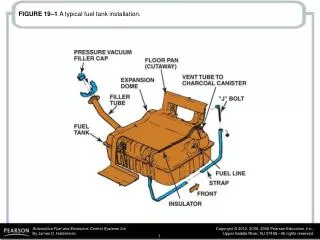
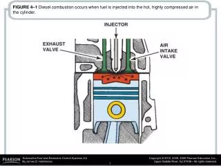
FIGURE 10–1 Typical brake system components showing disc brakes on the front and drum brakes on the rear. FIGURE 10–2 An exploded view of a typical drum brake assembly. FIGURE 10–3 The backing plate is the foundation of every drum brake.

E N D
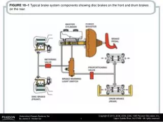
FIGURE 10–1 Typical brake system components showing disc brakes on the front and drum brakes on the rear.
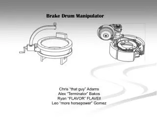
FIGURE 10–2 An exploded view of a typical drum brake assembly.
FIGURE 10–3 The backing plate is the foundation of every drum brake.
FIGURE 10–4 A labyrinth seal is created between the lip of the backing plate and the groove in the brake drum.
FIGURE 10–5 A keystone anchor allows the brake shoes to self-center in the drum.
FIGURE 10–6 Piston stops prevent the wheel cylinder from coming apart.
FIGURE 10–7 Cross-section of a wheel cylinder that shows all of its internal parts. The brake line attaches to the fluid inlet. The cup extender prevents the cup seal lip from collapsing when the brakes are released.
FIGURE 10–8 The pushrods are held in place by the rubber dust boots. As the wheel cylinder pistons move outward, the pushrods transfer the movement to the brake shoes.
FIGURE 10–9 Steelbrake shoes are made from two stampings welded together—the web and the lining table.
FIGURE 10–10 Tapered ends on the linings help to reduce brake noise.
FIGURE 10–11 Typical drum brake shoe and the names of the parts. (Courtesy of Allied Signal Automotive Aftermarket)
FIGURE 10–12 The primary (forward facing) brake shoe often has a shorter lining than the secondary shoe (rearward facing).
FIGURE 10–13 Primary shoe lining may vary depending on the application.
FIGURE 10–14 Riveted brake linings are quiet and reliable at high temperatures.
FIGURE 10–17 A typical drum brake assembly showing the support plate (backing plate), anchor pin, and springs.
FIGURE 10–18 A single spring-steel spring is used on some drum brakes.
FIGURE 10–20 A mechanical brake linkage is part of most drum brake assemblies.
FIGURE 10–21 An aluminium brake drum with a cast iron friction surface. The cooling fins around the outside help dissipate the heat from the friction surface to the outside air.
FIGURE 10–22 Self-energizing action can increase or decrease the stopping power of a brake shoe.
FIGURE 10–26 A typical dual-servo brake adjusting link assembly.
FIGURE 10–27 Dual-servo brake operation. The primary shoe on the left exerts a force on the secondary shoe on the right.
FIGURE 10–28 Dual servo action greatly increases the application force on the secondary shoe.
FIGURE 10–29 A cable-actuated starwheel adjuster. This type of adjuster makes the adjustment as the brakes are released.
FIGURE 10–30 A lever-actuated starwheel automatic adjuster. This type of adjuster makes the adjustment when the brakes are applied.
FIGURE 10–31 A link-actuated starwheel adjuster. This type of adjuster makes the adjustment when the brakes are released.
FIGURE 10–32 The operation of a typical self-adjuster. Notice that the adjuster actually moves the starwheel.
FIGURE 10–33 A cable-actuated starwheel adjuster with an over-travel spring.
FIGURE 10–34 A non-servo brake with a lever-actuated starwheel automatic adjuster on a leading shoe. This type of adjuster makes an adjustment as the brakes are applied.
FIGURE 10–35 A non-servo brake with a lever-actuated starwheel automatic adjuster on the trailing shoe. This type of adjuster makes the adjustment as the brakes are released.