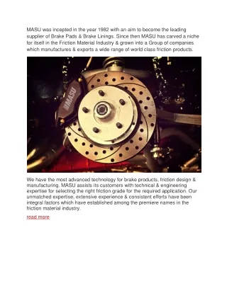
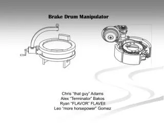
Brake Drum Manipulator
Brake Drum Manipulator. Chris “that guy” Adams Alex “Terminator” Bakos Ryan “FLAVOR” FLAVEll Leo “more horsepower” Gomez. Design Requirements/Objectives. The main purpose of this system is to improve ergonomics, increase productivity, and safety. Newly designed equipment should aid

Brake Drum Manipulator
E N D
Presentation Transcript
Brake Drum Manipulator Chris “that guy” Adams Alex “Terminator” Bakos Ryan “FLAVOR” FLAVEll Leo “more horsepower” Gomez
Design Requirements/Objectives The main purpose of this system is to improve ergonomics, increase productivity, and safety. Newly designed equipment should aid and be strong enough for lifting and manipulating brakes assembly.
Design Requirements/Objectives The manipulator must be able to pick up brake assembly from gravity roller conveyor and orient the assembly for installation on the axle. Manipulator must work with the current over head system which is an aluminum 7500 Knight bridge.
Design Requirements/Objectives Air brake chamber must be mounted inboard of the brake assembly as shown. Manipulator will be able to rotate, tilt and lift to take off and install brake assembly from input gravity roller conveyor to install on axle.
Roller Gravity Conveyors Bridges For Manipulators Onsite facilities and utilities Electrical, pneumatic, rail system, etc.
Design system break down • Securely clamp the brake assembly (~105 lbs) to manipulator assembly. • Once clamped lift the brake assembly off the roller conveyor (24 inches off the ground) to the height of the axel assembly (44 inches off the ground), a span of about 20 inches. • At axel height, tilt the assembly 90 degrees so that air brake chamber (pumpkin) is inboard in the axel. • Upon tilting the drum brake assembly 90 degrees, the axle will be rotated to a 3 o’clock position to facilitate the stud assembly. • Brake drum assembly must be securely held on hub to allow two studs to be inserted and tightened down before releasing from manipulator. • Release brake drum without causing damage to part, equipment or personnel.
Subsystems • Clamping onto the Drum • Linear movement • Tilt the Drum 90 degrees • Rotating Drum about the Axle
Linear movement The linear movement consists of a winch that will move the brake assembly from the gravity roller conveyor (24 inches off the ground) to the height of the axel assembly (44 inches off the ground), a span of about 20 inches.
Why is our manipulator better than others? • It meets all the design specifications; clamp, lift, tilt and rotate • It’s ergonomic; Optimally engineered so that when tilting or rotating, the brake drum feels weightless since we have designed it to rotate about the center of gravity therefore requiring little effort in maneuvering. • System pads can be assembled and disassembled to adapt to other brake drums. • The manipulator is made from off the shelf manufacturable materials and other pre-fabricated components to keep cost down and make interchangeability easy.