Manipulator Dynamics
Introduction to ROBOTICS. Manipulator Dynamics . Jizhong Xiao Department of Electrical Engineering City College of New York jxiao@ccny.cuny.edu. Outline. Homework Highlight Review Kinematics Model Jacobian Matrix Trajectory Planning Dynamic Model Langrange-Euler Equation Examples.

Manipulator Dynamics
E N D
Presentation Transcript
Introduction to ROBOTICS Manipulator Dynamics Jizhong Xiao Department of Electrical Engineering City College of New York jxiao@ccny.cuny.edu
Outline • Homework Highlight • Review • Kinematics Model • Jacobian Matrix • Trajectory Planning • Dynamic Model • Langrange-Euler Equation • Examples
Homework highlight • Composite Homogeneous Transformation Matrix Rules: • Transformation (rotation/translation) w.r.t. (X,Y,Z) (OLD FRAME), using pre-multiplication • Transformation (rotation/translation) w.r.t. (U,V,W) (NEW FRAME), using post-multiplication
(z’) (y’) (X’) Homework Highlight • Homogeneous Representation • A frame in space
Z3 Z1 Z0 Joint 3 X3 Y0 Y1 Z2 d2 Joint 1 X0 X1 X2 Joint 2 Y2 a0 a1 Homework Highlight • Assign to complete the right-handed coordinate system. • The hand coordinate frame is specified by the geometry of tool. Normally, establish Zn along the direction of Zn-1 axis and pointing away from the robot; establish Xn so that it is normal to both Zn-1 and Zn. Assign Yn to complete the right-handed system.
Review • Steps to derive kinematics model: • Assign D-H coordinates frames • Find link parameters • Transformation matrices of adjacent joints • Calculate kinematics matrix • When necessary, Euler angle representation
Review • D-H transformation matrix for adjacent coordinate frames, i and i-1. • The position and orientation of the i-th frame coordinate can be expressed in the (i-1)th frame by the following 4 successive elementary transformations:
Review • Kinematics Equations • chain product of successive coordinate transformation matrices of • specifies the location of the n-th coordinate frame w.r.t. the base coordinate system Orientation matrix Position vector
Jacobian Matrix Forward Jacobian Matrix Kinematics Inverse Jaconian Matrix: Relationship between joint space velocity with task space velocity Joint Space Task Space
Jacobian Matrix Jacobian is a function of q, it is not a constant!
Jacobian Matrix • Inverse Jacobian • Singularity • rank(J)<min{6,n}, • Jacobian Matrix is less than full rank • Jacobian is non-invertable • Occurs when two or more of the axes of the robot form a straight line, i.e., collinear • Avoid it
Trajectory Planning • Trajectory planning, • “interpolate” or “approximate” the desired path by a class of polynomial functions and generates a sequence of time-based “control set points” for the control of manipulator from the initial configuration to its destination. • Requirements: Smoothness, continuity • Piece-wise polynomial interpolate • 4-3-4 trajectory
Manipulator Dynamics • Mathematical equations describing the dynamic behavior of the manipulator • For computer simulation • Design of suitable controller • Evaluation of robot structure • Joint torques Robot motion, i.e. acceleration, velocity, position
Manipulator Dynamics • Lagrange-Euler Formulation • Lagrange function is defined • K: Total kinetic energy of robot • P: Total potential energy of robot • : Joint variable of i-th joint • : first time derivative of • : Generalized force (torque) at i-th joint
Manipulator Dynamics • Kinetic energy • Single particle: • Rigid body in 3-D space with linear velocity (V) , and angular velocity ( ) about the center of mass • I: Inertia Tensor: • Diagonal terms: moments of inertia • Off-diagonal terms: products of inertia
Velocity of a link A point fixed in link i and expressed w.r.t. the i-th frame Same point w.r.t the base frame
Velocity of a link Velocity of point expressed w.r.t. i-th frame is zero Velocity of point expressed w.r.t. base frame is:
Velocity of a link • Rotary joints,
Velocity of a link • Prismatic joint,
Velocity of a link The effect of the motion of joint j on all the points on link i
Kinetic energy of link i • Kinetic energy of a particle with differential mass dm in link i
Kinetic energy of link i Center of mass Pseudo-inertia matrix of link i
Manipulator Dynamics • Total kinetic energy of a robot arm Scalar quantity, function of and , : Pseudo-inertia matrix of link i, dependent on the mass distribution of link i and are expressed w.r.t. the i-th frame, Need to be computed once for evaluating the kinetic energy
Manipulator Dynamics • Potential energy of link i : Center of mass w.r.t. base frame : Center of mass w.r.t. i-th frame : gravity row vector expressed in base frame • Potential energy of a robot arm Function of
Manipulator Dynamics • Lagrangian function
Manipulator Dynamics The effect of the motion of joint j on all the points on link i The interaction effects of the motion of joint j and joint k on all the points on link i
Manipulator Dynamics • Dynamics Model
Manipulator Dynamics • Dynamics Model of n-link Arm The Acceleration-related Inertia matrix term, Symmetric The Coriolis and Centrifugal terms Driving torque applied on each link The Gravity terms
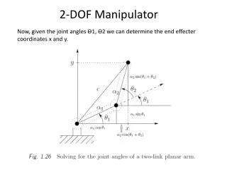
Example Example: One joint arm with point mass (m) concentrated at the end of the arm, link length is l , find the dynamic model of the robot using L-E method. Set up coordinate frame as in the figure
Example Kinetic energy
Example • Potential energy • Lagrange function • Equation of Motion
Example: Puma 560 • Derive dynamic equations for the first 4 links of PUMA 560 robot
Example: Puma 560 • Set up D-H Coordinate frame • Get robot link parameters • Get transformation matrices • Get D, H, C terms
Example: Puma 560 • Get D, H, C terms
Example: Puma 560 • Get D, H, C terms ……
Example: Puma 560 • Get D, H, C terms
Example: Puma 560 • Get D, H, C terms
Thank you! Homework 4 posted on the web. Due: Oct. 21, 2008 (Tue) Next class: Manipulator Control