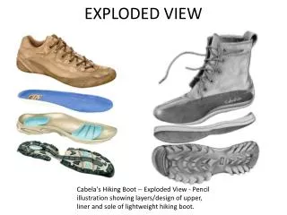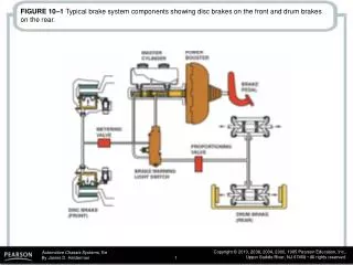
FIGURE 12.1 An exploded view of a typical disc brake assembly.
FIGURE 12.1 An exploded view of a typical disc brake assembly. FIGURE 12.2 Braking force is applied equally to both sides of the brake rotor.

FIGURE 12.1 An exploded view of a typical disc brake assembly.
E N D
Presentation Transcript
FIGURE 12.1 An exploded view of a typical disc brake assembly.
FIGURE 12.2 Braking force is applied equally to both sides of the brake rotor.
FIGURE 12.3Disc brakes can absorb and dissipate a great deal of heat. During this demonstration, the brakes were gently applied as the engine drove the front wheels until the rotor became cherry red.
FIGURE 12.4 Slots and holes in the brake linings help prevent gas and water fade.
FIGURE 12.5 The square-cut O-ring not only seals hydraulic brake fluid but also retracts the caliperpiston when the brake pedal is released.
FIGURE 12.6 Antirattle clips reduce brake pad movement and vibration.
FIGURE 12.7 Antivibration shims are used behind the pads on many disc brake caliper designs.
FIGURE 12.8 This brake caliper attaches to the front spindle.
FIGURE 12.9 A rear disc brake caliper often attaches to a mounting bracket on the rear axle housing.
FIGURE 12.11 To prevent noise, bent tabs on the backing plate hold some brake pads to the caliper housing.
FIGURE 12.12 Holes in the backing plate are a common method of locating a pad in the caliper.
FIGURE 12.13 Retainer springs lock the pad to the caliper piston to prevent brake noise.
FIGURE 12.14 The lining edges of some brake pads are tapered to help prevent vibration.
FIGURE 12.15Typical pad wear sensor operation. It is very important that the disc brake pads are installed on the correct side of the vehicle to be assured that the wear sensor will make a noise when the pads are worn.
FIGURE 12.16 Electrical wear indicators ground a warning light circuit when the pads need replacement.
FIGURE 12.17 Mold-bonded linings are commonly used in many applications.
FIGURE 12.18 Disc brake rotors can be either solid or vented.
FIGURE 12.19 (a) Many fixed caliper disc brakes use a simple retaining pin to hold the disc brake pads. (b) Removing the retainer pin allows the brake pads to be removed. (c) Notice the cross-over hydraulic passage that connects both sides of the caliper.
FIGURE 12.20 This floating caliper mounts on a separate anchor plate that bolts to the vehicle suspension.
FIGURE 12.21Hydraulic force on the piston (left) is applied to the inboard pad and the caliper housing itself.
FIGURE 12.22 Caliper flex can cause tapered wear of the brake lining.
FIGURE 12.23A typical single-piston floating caliper. In this type of design, the entire calipermoves when the single piston is pushed out of the caliper during a brake application.
FIGURE 12.24 Floating calipers are supported by rubber O-rings or plastic bushings.
FIGURE 12.25 Metal guide pins and sleeves are used to retain and locate floating calipers.
FIGURE 12.26 In a standard disc brake caliper, the squarecut O-ring deforms when the brakes are applied and returns the piston to its original (released) position due to the elastic properties of the rubber seal.
FIGURE 12.27 Exploded view of a typical sliding brake caliper.
FIGURE 12.29 Exploded view of a typical rear disc brake with an integral parking brake. The parking brake lever mechanically pushes the caliper piston against the rotor.
FIGURE 12.30 This single-piston brake caliper is mechanically actuated to serve as a parking brake.
FIGURE 12.31 Drum parking brakes are fitted inside the rotors on this vehicle equipped with rear disc brakes.