Understanding Memory Storage with Latches and Flip-Flops
Learn about latches, flip-flops, and state diagrams through a door lock example. Explore storing information, feedback, and state transitions in logic circuits. Understand D-latches, flip-flops, and edge triggering concepts.

Understanding Memory Storage with Latches and Flip-Flops
E N D
Presentation Transcript
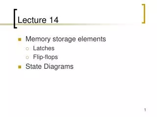
Lecture 14 • Memory storage elements • Latches • Flip-flops • State Diagrams
Example from last time • Door combination lock • Inputs: Sequence of numbers, reset, new • Outputs: Door open/close • Memory: Must remember combination • Memory: Must remember current state
"1" "0" "stored bit" How do we store information? • Feedback • Example: Two inverters can hold a bit (as long as power is applied) • What is missing? • How do we change the stored bit?
"remember" "load" "stored bit" "data" How do we store information? • Storing a new memory • Temporarily break the feedback path
S R Q0 0 hold0 1 01 0 11 1 disallow R Q Q' S Reset R Q Set S Q SR latch • Cross-coupled NOR gates • Can set (S=1, R=0) or reset (R=1, S=0) the output
S R Q0 0 hold0 1 01 0 11 1 disallow R Q Q' S Hold Race Reset Set Reset Set 100 R S Q Q' SR latch behavior
R 0 Q S Q' 0 SR latch is glitch sensitive • Static 0 glitches can set/reset latch • Glitch on S input sets latch • Glitch on R input resets latch
State diagrams • How do we characterize logic circuits? • Combinational circuits: Truth tables • Sequential circuits: State diagrams • First draw the states • States Unique circuit configurations • Second draw the transitions between states • Transitions Changes in state caused by inputs
SR=10 S R Q0 0 hold0 1 01 0 11 1 disallow SR=00 SR=01 SR=00 SR=10 Q Q'0 1 SR=01 Q Q'1 0 R Q SR=10 SR=01 SR=11 Q' S Q Q'0 0 SR=11 SR=11 SR=00 SR=11 SR=00 SR=01 SR=10 Q Q'1 1 possible oscillationbetween states 00 and 11 (when SR=00) Example: SR latch
SR=10 SR=00 SR=01 SR=00 SR=10 Q Q'0 1 Q Q'1 0 SR=01 Observed SR latch behavior • The 1–1 state is transitory • Either R or S “gets ahead” • Latch settles to 0–1 or 1–0 state ambiguously • Race condition non-deterministic transition • Disallow (R,S) = (1,1)
Input D Q Q CLK D ("data") latch • Output depends on clock • Clock high: Input passes to output • Clock low: Latch holds its output CLK D Qlatch
D Q R CLK S Q D Making a D latch
Input D Q Q CLK D flip-flop • Input sampled at clock edge • Rising edge: Input passes to output • Otherwise: Flip-flop holds its output • Flip-flops can be rising-edge triggered or falling-edge triggered CLK D Qff
Master D latch Slave D latch X Output Input D Q D Q CLK Master-slave D-type flip-flop • How to make into negative edge-triggered D-type flip-flop?
D Q Q D Q Q CLK Latches versus flip-flops CLK D Qff Qlatch CLK behavior is the same unless input changes while the clock is high
Rising-edge triggered D flip-flop Positive D latch Output Output Input Input D Q Output Output Q CLK Falling-edge triggered D flip-flop D D Q Q Negative D latch Q Q Output Output Input Input D Q Output Output Q CLK CLK CLK Terminology and notation
Edge triggering is difficult Label the internal nodes Draw a timing diagram Start with Clk=1 W X Q Clk Q’ Y Z D How to make a D flip-flop?
W X Q Clk Q’ Y Z D How to make a D flip flop? Falling edge-triggered flip-flop If Clk=1 then X=Y=0 and SR latch block holds previous values of Q,Q’, also Z=D’ and W=Z’=D. When Clk 0 then Y (set for SR latch block)becomes Z’=D and X (reset for SR latch block) becomes W’=D’ so Q becomes D. While Clk=0, if D switches then Z becomes 0 (because inputs to Z are D and D') and X and W hold their previous values and Y=X’=D as before.
Input(t) Q(t) Q(t + t) Input Q T Q 0 0 0 > 0 1 1 1 0 1 CLK 1 1 0 T ("toggle") flip-flop • Output toggles when input is asserted • If T=1, then Q Q' when CLK • If T=0, then Q Q when CLK