Lecture 14
Lecture 14. Two Simulation Codes: BATSRUS and Global GCM. BATSRUS (Block-adaptive tree solar wind Roe-type upwind scheme ) (Powell et al.,J. Comp. Phys., 154, 284,1999). Conservation of mass Faraday’s Law Total time rate of change of magnetic flux across a given surface S bounded by δ S.

Lecture 14
E N D
Presentation Transcript
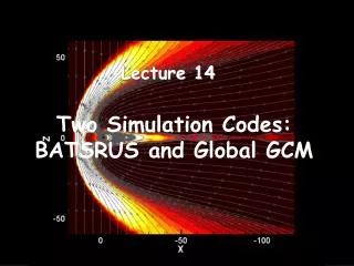
Lecture 14 Two Simulation Codes: BATSRUS and Global GCM
BATSRUS (Block-adaptive tree solar wind Roe-type upwindscheme) (Powell et al.,J. Comp. Phys., 154, 284,1999) • Conservation of mass • Faraday’s Law • Total time rate of change of magnetic flux across a given surface S bounded by δS
BATSRUS Equations • Although B is divergenceless it is kept in order to have all of the equations in normalized divergence form • Conservation of Momentum The second equation was derived from the first by using Ampere’s Law ( ) and vector identities.
BATSRUS Equations • Conservation of Energy g is the ratio of specific heats.
BATSRUS Ohm’s Law • Uses an ideal Ohm’s Law with η=0. • Achieves numerical stability by eliminating numerical noise.
BATSRUS Adaptive Grid • The grid is adaptive and Cartesian arranged using a tree data structure. • It consists of grid blocks each of which corresponds to a node of the tree. • The root of the tree is a coarse grid covering the entire region to be simulated. • In region where refinement occurs each block is divided into eight octants – cube is halved. • Each of the new blocks can be refined in the same way.
Adaption Continued • The decision on whether to refine the grid (or reduce the grid spacing) is made by comparison of local flow quantities with threshold values. • Local values of compressibility, rotationality and current density are used where V is the cell volume.
The Adaptive Grid The grid refinement for an actual simulation
Local Time Stepping • Time-accurate mode – each time step advanced according to the Courant condition. • Iterative local time stepping mode – each cell takes different time steps. • Converges to a steady state solution through unphysical intermediate states. • Upstream boundary conditions are held constant and a steady state magnetospheric configuration is derived for those upstream conditions and the dipole and corotation tilt. • No history to the solution – wrong for the magnetosphere. • For directly driven part of magnetospheric response method works.
BATSRUS Ionosphere • The Hall and Pedersen conductances are determined from the F10.7 flux. • Particle precipitation induced conductance was included. The conductance was determined from the local field-aligned current. • Ionospheric conductances and field-aligned currents derived from the assimilative mapping of ionospheric electrondynamics technique (AMIE). (Ridley et al., J. Geophys. Res., 106, A12, 30,067) • Ran the AMIE code 8500 times to get patterns of conductance, binned the results according to location and current density and fit the results.
BATSRUS Ionospheric Conductance and Field Aligned Currents • Simulation does not reproduce region 2 field-aligned currents. • Ionospheric boundary extends into the region where the R2 currents are generated. • R2 currents are thought to result from pressure gradients in the inner magnetosphere. Need even better resolution. • Contribution from gradient and curvature drift missing.
BATSRUS Coordinate System • Calculations are carried out in Geocentric Solar Magnetospheric (GSM) Coordinates. • X-axis from the Earth to the Sun • Y-axis is defined to be perpendicular to the Earth’s magnetic dipole so that the X-Z plane contains the dipole axis. • Z-axis is chosen to be in the same sense as the northern magnetic dipole. • The difference between the GSM and GSE is a rotation about the X-axis. • The rotation has the form below where θ is a function of time of day and time of year
OpenGCM • Originally developed by Jimmy Raeder at UCLA. • CCMC has a version he developed at the University of New Hampshire. • It is very similar to the current code used by Mostafa El- Alaoui at UCLA.
Open-GCM Magnetohydrodynamic Equations • Macroscopic plasma properties are governed by basic conservation laws for mass, momentum and energy in a fluid. Mass Momentum Energy* Faraday’s Law Gauss’ Law Ohm’s Law Ampere’s Law
Open-GCM Boundary Conditions • The MHD equations are solved as an initial value problem. • Solar wind parameters enter the upstream edge of the simulation and interact with a fields and plasmas in the simulation box. • Boundary conditions at the downstream edge, the north and south edges and the east and west edges are set to approximate infinity. • Downstream- where y represents the parameters in the MHD equations. • The bow shock frequently passes through the side and top and bottom boundaries. Here setting the derivative approximately parallel to the shock to zero works well.
Open-GCM Ionospheric Conductance Model • Solar EUV ionization • Empirical model- [Moen and Brekke, 1993] • Diffuse auroral precipitation • Strong pitch angle scattering at the inner boundary of the simulation-[Kennel and Petschek, 1966] • Electron precipitation associated with upward field-aligned currents (Knight, [1972] relationship but empirical models). • Conductance [Robinson et al, 1987]
The Open-GCM Electric Field where v is bulk velocity, B the magnetic field, J the current density, and η is the resistivity. • The resistivity where a is a small constant. The resistivity is turned on when the current density exceeds a threshold. This threshold has been calibrated so it only appears in strong current sheets. This avoids spurious dissipation.
Open-GCM Coordinate System • The Open-GCM calculations are in the Geocentric Solar Ecliptic Coordinate System (GSE). • In GSE the x-axis points toward the Sun • The Y-axis is in the ecliptic plane pointing toward dusk (i.e. opposite to planetary motion). • The z-axis is parallel to the ecliptic pole. • Relative to an inertial system this system has a yearly rotation.
Including the IMF Bx component in the Open-GCM Model • Special care must be taken when including the IMF BX in the calculations or . • Two approaches are used. • Some use a method developed by John Lyon and colleagues. They assume that the BX component is given by a linear combination of the other two field components where c and d are determined by least squares fitting to the observed solar wind time series. • Mostafa El-Alaoui developed a method thereby he carries out a minimum variance analysis and rotates the simulation domain into the minimum variance direction. The magnetic field is kept constant along the minimum variance direction thereby assuring that . • Both approaches only approximate BX.
MHD Models and the Ring Current • The ring current involves physics not included in MHD. For instance particles move around the Earth due to gradient and curvature drift motion. • Additional models must be used to include the ring current in the MHD models. • Empirically based ring current models can be added to the MHD models (e.g. the Fok ring current model). • Theoretical models can be added such as the Rice Convection Model which include the particle motion.