TOPIC
TOPIC. Failure in Landing Gear of Mirage 5 . TOPIC. Group members. Haroon Ahmed Mirza Muhammad Awais Rana Waqas Ali Khan. CONTENTS. INTRODUCTION MATERIALS PARTS OF LANDING GEAR SHOCK DAMPERS/TORQUE LINKS FAILURE CALCULATION OF FORCES


TOPIC
E N D
Presentation Transcript
TOPIC Failure in Landing Gear of Mirage 5 TOPIC
Group members • HaroonAhmed Mirza • Muhammad Awais • RanaWaqas Ali Khan
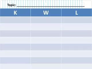
CONTENTS • INTRODUCTION • MATERIALS • PARTS OF LANDING GEAR • SHOCK DAMPERS/TORQUE LINKS • FAILURE • CALCULATION OF FORCES • ANALYSIS • SAFETY ACTIONS
INTRODUCTION OF LANDING GEAR Purpose :- Main Purpose of landing gear is take off ,taxi and as the name indicates for landing of air craft
INTRODUCTION OF LANDING GEAR Landing gear is also called under carriage and the type of undercarriage is tricycle under carriage . In tricycle under carriage there is • Nose Wheel Landing Gear. • Main Landing Gear .
MATERIALS Materials with high strength to weight ratio are used in landing gears . Following are the materials used • Aluminum alloys • Steel alloys • carbon • Titanium
PARTS Following are the parts of landing gear • Shock struts and torque links • Braces and locks • Air ground logic • Brakes • Temperature indication
SHOCK DAMPERS/ORQUE LINKS The shock struts/dampers are designed to absorb the forces which are created when the aircraft touches down on the runway. These forces need to be transferred to the aircraft structure. When the aircraft is taxiing on the ground, the shock struts absorb the shocks created by unevenness in the taxiways. The shock strut also prevents the aircraft from bouncing up after touchdown.
SHOCK DAMPERS/TORQUE LINKS • Torsional loads are transferred to upper strut by torque links. • Torque link prevent rotation about vertical axis . • Maintain wheel alignment.
FAILURE • The left main landing gear of air craft begin to shimmy immediately after touch down Brakes were applied to slow the aircraft in an attempt to control the shimmy, but the oscillations continued until both left main wheels and brake assemblies separated from the axles . Examination revealed that the upper torque link failed within the some yards of feet of the landing roll, and the wheels separated about 1ooo feet from touchdown.
CALCULATION OF FORCES • Weight of plane = 7050 kg • Landing speed = 290 km/h • Angle when plane is landing =4 degrees • Vertical speed = sin 4 * 290 km/h =20.22 when the main landing gear will touch the runway it will create an impulse , as we know that impulse is equal to change in momentum. Formula = ∑f .∆t=m∆t ① average speed =10.11 km/h
CALCULATION OF FORCES Length of lower strut =1 ft Length of upper strut =1.5 ft Distance covered by dampers after impulse=0.5ft Time taken in covering the distance t=o.5/1o.11 = 0.05 s
CALCULATION OF FORCES • From equation ① ∑ F *0.049 =7050 * 20.22 ∑ F = 30398934.7 KN After the first impulse torsion will be generated and formula for calculating it will be
ANALYSIS • The left main gear began to shimmy immediately after touchdown, resulting in failure of the upper torque. • The loose fit of the torque link bushings and pins from the previous overhaul prevented the torque links from controlling and eliminating the shimmy. • The nitrogen pressure in the oleo exceeded the pressure specified in the maintenance manual, and contributing to the oleo’s stiffness.
SAFETY ACTIONS • THRUST REVERSER:- is used to reduce wheel braking energy required landings and aborted takeoffs . • Avoid unnecessary heavy braking during the landing, if possible, to further reduce braking loads.
SAFETY ACTIONS • All landing gear will have had the nitrogen pressures rechecked and serviced in strict accordance with the maintenance manual will, to reduce the possibility of increased stiffness from over-serviced oleos. • 2. All undercarriages for which the status of the torque links cannot be confirmed as having been overhauled to "new" limits will have the mid-life inspection performed as soon as possible.