Download
1 / 27
270 likes | 468 Vues
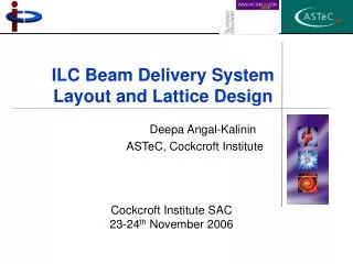
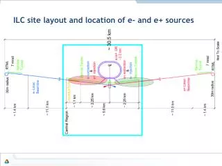
ILC site layout and location of e- and e+ sources. The Baseline ILC Electron Source . Electron source provides polarized electron beam and consists of all systems from source laser to 5 GeV injection to damping rings. ( 325 MHz SHB). 325 325. Page 3. Electron source parameters.

E N D
The Baseline ILC Electron Source Electron source provides polarized electron beam and consists of all systems from source laser to 5 GeV injection to damping rings. ( 325 MHz SHB) 325 325 Page 3
ILC TDR positron source location Target for e+ production 147 m helical undulator for photon production Optical Matching Device for e+ capture PBSTR 400MeV-5GeV PPA (125-400MeV) Photon collimator for pol. upgrade PCAP Damping ring g Main e- beam from electron main linac gdump PLTR: Energy compression and spin rotation PTAPA (~125MeV) e- dump Main e- beam to IP 150 GeV beam to dump 5
ILC Positron source schematic with key components Target for e+ production Optical Matching Device for e+ capture enhancement 147 m helical undulator for photon production Positron Energy Booster (PBSTR): Cryo-modules to boost e+ energy from 400MeV up to 5GeV Photon collimator for pol. upgrade • When Ecm is bellow 300GeV, the machine will be working in 10Hz mode where a dedicated 5Hz 150GeV positron production beam will be interlaced with 5Hz luminosity production beam Damping ring g Main e- beam from electron main linac gdump e- dump Positron Linac to damping Ring (PLTR): Energy compression and spin rotation Main e- beam to IP Used e+ production beam to dump Positron Target Area Pre-Accelerator (PTAPA ): L-band normal conducting RF accelerator to accelerate e+ beam up to ~125MeV Positron Pre-Accelerator (PPA): Normal conducting L-band RF accelerator to accelerate e+ beam from 125MeV up to 400MeV Positron separation and capture section: To separate e+ from e- and g To clean up e+ which will not be accepted by damping
Helical undulator Lattice parameter Basic parameters • The TDR baseline undulator has active length of 147m • The undulator will work at lower B field for Ecm=350GeV and 500GeV to bring the polarization back to ~30% while keep the positron yield at 1.5 (50% margin allowed for unexpected losses) • The lattice has reserved extra space for polarization upgrade(73.5m long active length) • The undulator magnet and crymodule has successfully prototyped at RAL
Undulator prototyping • RAL group has successfully fabricated two identical long undulators, each 1.75m in length, which have been magnetically tested and proven easily to achieve the field strength required • The RAL team has since incorporated both of these undulators into a single 4 m-long cryogenic module (which operates at -269 C) of the design required by ILC
Photon collimator • A photon collimator is not required for the TDR baseline • As part of positron source upgrade study, DESY team developed a photon collimator design. With the designed photon collimator, positron source polarization can be increased from ~30% up to 50-60% depending on the colliding beam energy
Target system • The positron-production target is a rotating wheel made of titanium alloy (Ti6Al4V). • The diameter of the wheel is 1m and the thickness is 0.4 radiation lengths (1.4 cm). • During operation the outer edge of the rim moves at 100 m/s.
Target system related issues • Vacuum seal • Two types of vacuum seals, Rigaku and FerroTech, have been tested at LLNL. Rigaku seal wasn’t able to run at 2000RPM. FerroTech seals each has its own individual personality; all have out gassing spike; off-the-shelf models do not seem to be well designed. • Need to partner with FerroTech to improve their design. • However, a differential pumping can be used as a back up scheme • Shockwaves and thermal dynamic • Energy deposition causes shockwaves in the material. If shock exceeds strain limit of material chunks can spall from the face • The SLC target showed spall damage after radiation damage had weakened the tungsten target material. • Initial calculations from LLNL had shown no problem in Titanium target • ANSYS simulation at DESY is underway and need to be further confirmed by experiment and/or simulation from different institute. • Future R&D • Target system prototype and test will continue at LLNL • Shockwave damage simulation will continue and need to develop and carry out an experiment test.
Target area shielding and target remote handling • The target will be highly activated after one year of operation. • With the nominal150kW photon beam, after 5000 hours of operation and 1 week of shutdown, the equivalent dose rate at 1m from the target wheel will be approximately 170 mSv/h. Concrete shielding of 0.8m thick around the target is sufficient fully to contain the radiation associated with the beam and with the subsequently activated materials. • A remote-handling system is used to replace the target, OMD and the 1st 1.3m NC RF cavities.
Optical Matching Device (OMD) • ILC TDR baseline OMD is a flux concentrator. • It works by pulsing the exterior coil to enhance the magnetic field in the center. • Similar device built 40 years ago. Cryogenic nitrogen cooling of the concentrator plates. • A room temperature device has been designed and prototyped at LLNL
Positron source Target Area Pre-Accelerator(PTAPA) • The positron capturing region RF is consist of two 1.3m long L-band standing wave structure and three 4.3m long L-band travelling wave structure. • The background solenoid field is 0.5T • The center of positron beam will be accelerated up to 125MeV at the end of this section. PTAPA RF and solenoids Typical longitudinal distribution of e+ at end of capturing section
Positron separation beamline (PCAP section) is used to separate positrons beam from electrons and g beam. The electron beam and g beam will be dumped into the e- dump and g dump. The positrons with energy too low and too high will be cleaned up in this chicane using collimators. The length of this section is 74m Positron separation Target for e+ production 147 m helical undulator for photon production Optical Matching Device for e+ capture PBSTR 400MeV-5GeV PPA (125-400MeV) Photon collimator for pol. upgrade PCAP Damping ring g Main e- beam from electron main linac gdump PLTR: Energy compression and spin rotation PTAPA (~125MeV) e- dump Main e- beam to IP 150 GeV beam to dump Positron separation beamline Typical longitudinal distribution after PCAP
Positron Pre-Accelerator (PPA) • ILC positron pre-accelerator is consist of eight 4.3m long L-band room temperature travelling wave structure surrounded by 0.5T solenoids. • PPA accelerate the positron beam from 125MeV up to 400MeV. PPA beamline Typical longitudinal distribution at end of PPA
Positron Booster Beamline (PBSTR) Matching section Matching to PTRANH • Positron booster beamline is designed to accelerate positron beam energy from 400MeV up to 5GeV. • There are 3 type of cryomodules used in PBSTR. • 4C4Q which has 4 SCRF linacs and 4 quads. 6 units are used in the 1st section • 8C2Q which has 8 SCRF linacs and 2 quads. 8 units are used in the 2nd section • 8C1Q which has 8 SCRF linacs and 1 quad. 12 units are used in the 3rd section PBSTR1: 400MEV TO 1082.5649MEV PBSTR2: 1082.5649MEV TO 2507.0321 MeV PBSTR3: 2507.0321 MeV to 5GeV
Transfer beamline • There are two positron transfer beamline • 400MeV transfer beamline(PTRAN). It is a 479m long FODO lattice between PPA and PBSTR beamline • 5GeV transfer beamline (PTRANH). • Total number of quads: 79 • Total length of beamline: 934.23m Typical longitudinal distribution at end of PTRANH
Positron Linac to Damping Ring (PLTR) beamline • PLTR beamline has two main functions: Energy compression and Spin rotation • At the beginning of PLTR, there is one horizontal chicane for introducing the needed chirp for energy compressor. • The 1st horizontal arc after the chicane will bend the beam by 23.8 degrees and rotates the spin axis by 270 degrees in horizontal plane. • An energy compressor using a 9C0Q crymodule is installed to compress the beam energy spread into the damping acceptance window. • Following the energy compressor, a spin rotator with 8.3m long 3.16T super conducting solenoid is used to rotate the spin into vertical so that it can be preserved in the damping ring Floor map of PLTR beamline
Energy Compressor • TDR baseline energy compressor uses a cryomodule with 9 cavities and no quads. Each cavity has a voltage of 25MV. • The total length of cryomodule is 12.474m including flanges and interconnect pipes. (a) (b) Typical longitudinal distribution before(a) and after(b) energy compressor
Beamline Lattice • New lattice design has been done to comply with the new layouts as follow.
Optics parameter of the new ILC positron source beamline lattice
TeV upgrade scenarios • Scenarios has been Studied by both DESY and ANL • Proposed that keep everything the same (Target, OMD), but the undulator change to K=1, lu=4.3cm
Polarization upgrade • The ILC baseline positron source has an active undulator length of 147m while the lattice/layout of ILC positron source have left enough space for 231m effective undulatorlength. • The extra space can be used for additional undulator modules for polarization upgrade • A multi stage photon collimator design for polarization upgrade has been developed at DESY • Simulation study at DESY has shown that with their multi stage photon collimator design, polarization of positron source can be increased up to 50-60% depends on the colliding beam energies. 27
Issues with ILC positron sources • Risk assessments for the e+ system: • Undulator (OK, more RD needed for different scenarios other than Baseline) • Photon Collimators (good progress made, need a engineering design and prototyping) • Capturing magnets (design done, prototyping almost done) • Target (Rotating under magnetic field tested, vacuum seal being tested, shockwave damage simulation needs further confirmation) • Pre-accelerator (done) • RH (Engineering design done). • Lattice (Done, can be refined). • TeV upgrade option is viable for positron sources without any change to other parts of machine except the undulator.