Download

1 / 22
220 likes | 348 Vues
Wavelength Diversity. Brandoch Calef. Introduction. Wavelength diversity = Imaging using simultaneous measurements at different wavelengths. Why should this help? Diversity: the PSF is different in each band Wavefront estimation at longer wavelengths is easier How could it be used?

E N D
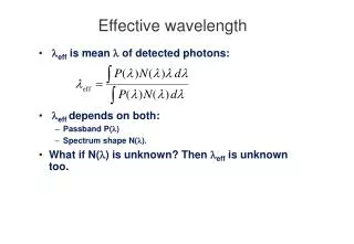
Wavelength Diversity Brandoch Calef
Introduction • Wavelength diversity = Imaging using simultaneous measurements at different wavelengths. • Why should this help? • Diversity: the PSF is different in each band • Wavefront estimation at longer wavelengths is easier • How could it be used? • Collect simultaneously in multiple bands, postprocess all data together by coupling wavefront phases. See work of Stuart and Doug. • Or: recover wavefront in one band (e.g. LWIR) and use it to partially correct other band (e.g. with a DM). Star observed in LWIR exhibits speckle
Spectral coverage at AMOS raw LWIR raw ASIS raw ASIS 4 μm—5 μm raw NIRVIS raw LWIR AMOS sensors can collect simultaneously from visible to LWIR. 1—1.2 μm 480—660 nm 700—950 nm 11 μm—12 μm
IR image limited by diffraction MFBD processing of simulated MWIR (3.5 μm) data: At longer wavelengths, high spatial frequencies are lost due to diffraction. Resulting reconstructed image lacks fine detail.
Visible image limited by poor wavefront estimate MFBD processing of simulated visible (500 nm) data: At shorter wavelengths, MFBD becomes trapped in a local maximum of the cost function and fails to find true wavefront → Recovered image has artifacts.
Wavelength diversity:linking spectral bands • Each wavelength experiences ~same optical path difference (OPD) due to atmospheric turbulence • Wavefront phase is θλ = OPD × 2π/λ, point-spread function is |F[P exp(iθλ)]|2 Longer wavelength: turbulence less severe,diffraction more severe Longerwavelength Shorter wavelength: turbulence more severe,diffraction less severe Shorterwavelength OPD in telescope pupil
Spectral variation of imagery OPD can be linked from band to band, but images cannot: To demonstrate insensitivity to spectral variation, use satellite defined in two bands for wavelength-diverse processing example: 800 nm 4.7 μm 11 μm 500 nm 3.5 μm
Combination of sensors yields better reconstructed image Wavelength-diverse MFBD processing of visible and MWIR data: MWIR only Visible only Joint reconstruction Two reconstructions, one in each band
OPD invariance breakdown: diffraction • Basic assumption in coupling phase at different wavelengths is thatand that OPD is not a function of wavelength. But OPD actually does depend on wavelength to some degree. • Geometrical optics: OPD is sum of delays along path. But diffraction is wavelength-dependent. Mean-square phase error between λ1 and λ2 due to neglected diffraction:in rad2 at λ1 where ki= 2π/λi, h0 = telescope altitude, h1 = top of atmosphere, x= zenith angle, D = diameter (Hogge & Butts 1982).
OPD invariance breakdown: diffraction 600 nm OPD error due to diffraction as function of wavelength, λ2=10 µm, r0=5 cm,zenith angle=30° OPD error due to diffraction as function of wavelength, λ2=500 nm, r0=5 cm,zenith angle=30° Wavefront error in waves rms at λ1 (λ1) (λ1) OPD error due to diffraction as function of r0,λ1=800 nm,λ2=10 µm,zenith angle=30° OPD error due to diffraction as function of zenith angle, λ1=800 nm,λ2=10 µm,r0=5 cm
OPD invariance breakdown:path length error • Geometrical approximation:Wavelength dependence of n is usually ignored, but can be significant for wavelength diversity.Assume n is separable in λ and (z, x). Tilt-removed mean-square phase error due to path length error isin rad2 at λ1. Should be at least partially correctible based on approximate knowledge of n(λ). n-1 Mathar, “Refractive index of humid air in the infrared,” J. Opt. A9 (2007)
OPD invariance breakdown:path length error Wavefront error in waves at λ1 OPD error as function of wavelength, λ2=10 µm,r0=5 cm, zenith angle=30° OPD error as function of wavelength, λ2=500 nm, r0=5 cm, zenith angle=30° (λ1) (λ1) OPD error as function of r0,λ1=800 nm,λ2=10 µm,zenith angle=30° OPD error as function of zenith angle, λ1=800 nm,λ2=10 µm, r0=5 cm
OPD invariance breakdown:chromatic anisoplanatism • Different colors follow different paths through atmosphere: • Illustration not to scale! Actual pupil displacement at top of atmosphere ~few cm except at very low elevation. • Mean-square phase error between λ1 and λ2 due to chromatic anisoplanatismin rad2 at λ1 where a(h) is air density at height h (Nakajima 2006). top of atmosphere observatory Projected pupils diverge → OPD depends on wavelength
OPD invariance breakdown:chromatic anisoplanatism Wavefront error in waves at λ1 OPD error as function of wavelength, λ2=10 µm,r0=5 cm, zenith angle=30° OPD error as function of wavelength, λ2=500 nm, r0=5 cm, zenith angle=30° Totals assume independent error contributions. (λ1) (λ1) OPD error as function of r0,λ1=800 nm,λ2=10 µm,zenith angle=30° OPD error as function of zenith angle, λ1=800 nm,λ2=10 µm, r0=5 cm
OPD invariance breakdown is small relative to turbulence Wavefront error in waves at λ1 Dominant error source is almost every case is path length error, which is partially correctible If wavefront is measured at 10 µm, total error at 800 nm about ¼ wave, increases rapidly for shorter wavelengths, vs. 1.29 waves atmospheric turbulence OPD error as function of wavelength, λ2=10 µm,r0=5 cm, zenith angle=30° OPD error as function of wavelength, λ2=500 nm, r0=5 cm, zenith angle=30° (λ1) (λ1) OPD error not sensitive to elevation angle above 40 degrees OPD error as function of r0,λ1=800 nm,λ2=10 µm,zenith angle=30° OPD error as function of zenith angle, λ1=800 nm,λ2=10 µm, r0=5 cm
Cramér-Rao bounds on variance of wavefront estimate Next step: Characterize effect of radiometry/sensor noise on wavefront estimate with Cramér-Rao bounds. Renderings from SVST (TASAT), range to satellite (SEASAT) ~450 km Includes solar spectral irradiance, atmospheric extinction, thermal foreground Δλ/λ = 1/8, D=3.6 m, 1/60 sec integration time, r0=6 cm at 500 nm, telescope optics throughput = 30% at all wavelengths
CRB caveats True OPD OPD estimated in MWIR • Calculating CRB from pseudoinverse of full FIM is not consistent from band to band • Here only first 88 Zernikes beyond piston, tip, and tilt participate. Residual rms OPD ≈ 1830 nm! Possibly better approach would be to integrate Fisher information matrix over residual wavefront. • CRB results here provide lower bounds and illustrate trends. vs.
CRBs: single wavelengths 3.5 µm 4.7 µm MWIR: low signal, high noise 11 µm 9.9 µm LWIR: high SNR, low sensitivity to wavefront Aberrations very small in LWIR, somodulation corresponding to Zernikeorders is evident. NIR/SWIR: moderate SNR, high sensitivity to wavefront 2 µm 990 nm
CRBs: NIR + second band 800 nm +second band(988 nm – 11µm)
CRBs: 11 µm + second band 11µm +second band(988 nm – 9.9 µm)
Summary of CRB analysis • LWIR preferable to MWIR • Two LWIR channels preferable to one LWIR + one MWIR • SNR trumps diversity, perhaps because object is independent in each band • NIR/SWIR results much better than longer wavelengths, but probably not achievable because of local minima traps.
Conclusions and future steps • Wavelength-diverse MFBD is a promising technique for combining data from multiple sensors to yield a higher-quality reconstructed image. • “Diversity” offered by multi-wavelength imaging is less important than the fact that wavefront estimation is just easier at longer wavelengths • Local minima traps at shorter wavelengths, even in joint processing with longer wavelengths • Coupling between bands is not sufficiently strong unless some coupling of images is assumed (compare with phase diversity) • For a reasonable range of conditions, the OPD changes ¼ wave or less (rms @ 800nm) between 800 nm and 10 µm, potentially half of this if path length error can be approximated. This is a small fraction of the total wavefront error. • CRB analysis shows greater advantage in using LWIR bands than MWIR bands. Good characterization of the LWIR path is likely to be critical. • Experimental studies: • On 1.6 m telescope using GEMINI (visible) and ADET (1-2 μm) cameras • On AEOS 3.6 m using range of sensors from visible to LWIR