Low Level RF Status
Explore the status and details of the LLRF system controls including PAD, PAC, VME feedback, software testing, and documentation. Get insights on software functionality, operational modes, and calibration processes for optimized performance.


Low Level RF Status
E N D
Presentation Transcript
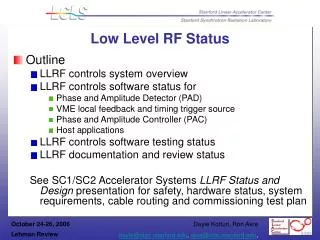
Low Level RF Status • Outline • LLRF controls system overview • LLRF controls software status for • Phase and Amplitude Detector (PAD) • VME local feedback and timing trigger source • Phase and Amplitude Controller (PAC) • Host applications • LLRF controls software testing status • LLRF documentation and review status See SC1/SC2 Accelerator Systems LLRF Status and Design presentation for safety, hardware status, system requirements, cable routing and commissioning test plan
Status of Software for Injector Turn-on • PAD Software • Operational • PAC Software • Operational • Local Feedback (in VME) • Data analysis shows simple feedback algorithm will work. • Optimization of algorithm continues. • Time measurement: measure time needed for data acq, for transfer to VME, for VME processing, for transfer to PAC. • Time measurement: needed for multiple local loops. Eg. Measure scalability from 1 to N instances. • This IOC needs to be SLC-aware • This IOC uses EVR and needs to set up trigger delays in response to timing events • RF Gun Temperature Feedback • In Design • Calibration and Test • Operational • Host Applications • In process of specifying • Storing of boot params, serial numbers, etc in flash or on the board for PAD and PAC
PAD Software • Different LLRF apps need different calculations • There are 5 different algorithms: • AVG+STD – calculate average I and Q and variance of I and Q • RF WF – calculate average I and Q • WF – calculate average of sample • RF WF2 – calculate average I and Q of two samples • IQ Cal – send 64K raw data waveform • Each channel on a PAD can run a different algorithm with its own sample size and offset • Each PAD can run in CALIBRATION or RUNNING mode, which use different algorithms
PAC Software • PACs can run in either CALIBRATING or RUNNING mode. A state machine keeps track. • If CALIBRATING, calibration waveforms are loaded into FPGA and I and Q gains and offsets can be adjusted. • If RUNNING, I and Q gains and offsets are fixed, operational waveforms are loaded into FPGA and I and Q adjustments can be applied at the operational frequency.
VME Software • Generic Feedback algorithm: • Phase and amplitude are calculated from I and Q averages from each channel of the PAD • Phases are corrected by phase offset correction • Amplitudes are corrected by amplitude power correction • Phase and amplitudes are weighted by configurable weighting factors to determine one average phase and amplitude • Pavg=(P0*PWT0 + P1*PWT1 + P2*PWT2 + P3*PWT3)/4*(ΣPWTi) • Aavg=(A0*AWT0 + A1*AWT1 + A2*AWT2 + A3*AWT3)/4*(ΣAWTi) • Local or global feedback corrections are applied (0 < A <= 1) • Pcor = A(Pdes – Pact) + (1-A)Pcorn-1 • Pcorn+1 = A(Pdes n+1 – Pactn+1) + (1-A)Pcorn • For amplitude, (Pdes – Pact) is replaced by Pdes/Pact • Corrected phase and amplitude is converted to I and Q • Corrected I and Q values are sent to PAC
VME Software • Beam Phasing Cavity algorithm (for Laser Timing): • Two sets of I and Q averages arrive (since there are two windows of interest) • Phase1 is calculated from I1 and Q1 • Phase2 is calculated from I2 and Q2 • Measured beam phase is the y-intercept of the equation to the line of phase as a function of FIFO position • Frequency is the slope of the line • Amplitude is calculated from I1 and Q1 (only) • Phase is corrected by phase offset correction • Amplitude is corrected by amplitude power correction • Local feedback corrections are applied • Corrected phase and amplitude is converted to I and Q • Corrected I and Q values are sent to laser PAC
Beam Phase Cavity: calculation of freqency and phase from a line through 2 points
VME Software • Other calculations • For RF Reference Distribution • Phase and amplitude are calculated from I and Q averages from each channel of the PAD • Phases are corrected by phase offset correction • Amplitudes are corrected by amplitude power correction • Standard deviation of I and Q is calculated from I and Q variances from each channel of the PAD
Host Applications • Generic • Correlation plots • Calibration of power levels using beam energy • Distribution System • Rotate Phase 360 degrees • Monitor Phase Errors in Dividers • Correct Divider Phase Errors • PAC • Calibration Mode Operation • Generate and Load Waveforms • Panels for Phase and Amplitude Adjustment • PAD Testing • Crosstalk, SNR, Noise Floor • Sine Wave Histogram • Panels for Phase and Amplitude Monitoring • Local Feedback Control Panels
Status of Documentation + Reviews • All documentation and reviews are accessible from LLRFhomepage Recent milestones: • LLRF Control Design Specification • This Engineering Specification Document was signed off by Project Office on 9/27/2006. • LLRF Final Design Review • This review was held on 9/19/2006. • The scope of the review covered: • RF Distribution Reference System for Injector Commissioning • RF System for Injector Commissioning • PAD • PAC • VME • These were the goals given to the committee last September: • Injector RF turn on is January 3, 2007. The designs of the prototype PADs and PACs have been built and tested. Fabrication is scheduled for October, 2006. Please review analysis of test data and the proposed design and comment on the proposed systems' ability to meet LCLS specifications. • Review our test plans and suggest improvements
Lab Test SetupReference, PAC, PAD The LCLS RF system duplicated in the lab and used for testing of PADs and PACs. At least two of each frequency generation chassis is built to measure phase noise levels. Most components will have development chassis which can be used as a spare.
LCLS New Reference System Lab Measurements Lab Tests Show Reference System Noise Levels Meet All LCLS Requirements 2856MHz = 70fSrms 2830.5MHz = 70fSrms 25.5MHz = 2pSrms 102MHz = 2pSrms 2856MHz : 22fSrms 10Hz to 10MHz 2830.5MHz : 22fSrms 10Hz to 10MHz John Byrd - LBNL 25.5MHz : 152fSrms 10Hz to 1MHz 102MHz : 281fSrms 10Hz to 10MHz
SLAC Linac RF – New Control The new control system will tie in to the IPA Chassis with 800W of drive power available. The RF Reference will be from the new RF reference system. Solid State Sub-Booster PAC I and Q will be controlled by the PAC chassis, running 16bit DACs at 102MHz. Waveforms to the DACs will be set in an FPGA through a microcontroller running EPICS on RTEMS. Existing System
Linac 21-1 Test Set-up Power Coupled out from 476MHz MDL drives a 476MHz Amplifier which feeds a 6X Multiplier from 476MHz to 2856MHz. The 2856MHz out drives both the LO generator and the PAC. The 2830.5MHz LO and 102MHz CLK Generator supplies the LO and CLK to the PAD. A CLK output of the PAD drives the PAC CLK. The PAC output drives the SSSB. The SSSB drives the existing IPA chassis The klystron output coupler is used to measure phase and amplitude with the new PAD.
Linac 21-1 Test Results Tests were done in the gallery with no temperature regulation on cables. Average RMS value of 2 second sliding average is 0.068 degrees. Exponential Smoothing Yields the Following Results. Lowest noise is with a time constant of about 2 points.