Download

1 / 84
850 likes | 1.03k Vues
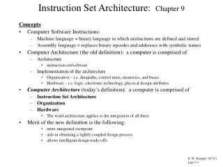
Chapter 2 Instruction Set Architecture. Chapter Outline. Machine instructions and program execution Addressing methods for data operands Assembly-language representation for instructions, data, and programs Stacks and subroutines. Memory Organiz a tion.

E N D
Chapter Outline • Machine instructions and program execution • Addressing methods for data operands • Assembly-language representation for instructions, data, and programs • Stacks and subroutines
Memory Organization • Memory consists of many millions of cells • Each cell holds a bit of information, 0 or 1 • Information usually handled in larger units • A word is a group of n bits • Word length can be 16 to 64 bits • Memory is a collection of consecutive wordsof the size specified by the word length
Word and Byte Encoding • A common word length is 32 bits • Such a word can store a 32-bit signed integeror four 8-bit bytes (e.g., ASCII characters) • For 32-bit integer encoding, bit b31 is sign bit • Words in memory may store data or machine instructions for a program • Each machine instruction may requireone or more consecutive words for encoding
Addresses for Memory Locations • To store or retrieve items of information,each memory location has a distinct address • Numbers 0 to 2k- 1 are used as addressesfor successive locations in the memory • The 2k locations constitute the address space • Memory size set by k (number of address bits) • Examples: k = 20 implies 220 or 1M locations,k = 32 implies 232 or 4G locations
Byte Addressability • Byte size is always 8 bits • But word length may range from 16 to 64 bits • Impractical to assign an address to each bit • Instead, provide a byte-addressable memory that assigns an address to each byte • Byte locations have addresses 0, 1, 2, … • Assuming a word length is 32 bits,word locations have addresses 0, 4, 8, …
Big- and Little-Endian Addressing • Two ways to assign byte address across words • Big-endian addressing assigns lower addresses to more significant (leftmost) bytes of word • Little-endian addressing uses opposite order • Commercial computers use either approach, and some can support both approaches • Addresses for 32-bit words are still 0, 4, 8, … • Bits in each byte labeled b7 … b0, left to right
Word Alignment • # of bytes per word is normally a power of 2 • Word locations have aligned addresses if they begin at byte addresses that are multiples of the number of bytes in a word • Examples of aligned addresses: 2 bytes per word ⇒ 0, 2, 4, … 8 bytes per word ⇒ 0, 8, 16, … • Some computers permit unaligned addresses
Memory Operations • Memory contains data & program instructions • Control circuits initiate transfer of data and instructions between memory and processor • Read operation: memory retrieves contents at address location given by processor • Write operation: memory overwrites contents at given location with given data
Instructions and Sequencing • Instructions for a computer must support: • data transfers to and from the memory • arithmetic and logic operations on data • program sequencing and control • input/output transfers • First consider data transfer & arithmetic/logic • Control and input/output examined later • Introduce notation to facilitate discussion
Register Transfer Notation • Register transfer notation is used to describe hardware-level data transfers and operations • Predefined names for procr. and I/O registers • Arbitrary names for locations in memory • Use […] to denote contents of a location • Use ← to denote transfer to a destination • Example: R2 ← [LOC] (transfer from LOC in memory to register R2)
Register Transfer Notation • RTN can be extended to also showarithmetic operations involving locations • Example: R4 ← [R2] + [R3] (add the contents of registers R2 and R3, place the sum in register R4) • Right-hand expression always denotes a value, left-hand side always names a location
Assembly-Language Notation • RTN shows data transfers and arithmetic • Another notation needed to representmachine instructions & programs using them • Assembly language is used for this purpose • For the two preceding examples using RTN,the assembly-language instructions are: Load R2, LOC Add R4, R2, R3
Assembly-Language Notation • An instruction specifies the desired operation and the operands that are involved • Examples in this chapter will use English words for the operations (e.g., Load, Store, and Add) • This helps emphasize fundamental concepts • Commercial processors use mnemonics,usually abbreviations (e.g., LD, ST, and ADD) • Mnemonics differ from processor to processor
RISC and CISC Instruction Sets • Nature of instructions distinguishes computer • Two fundamentally different approaches • Reduced Instruction Set Computers (RISC) have one-word instructions andrequire arithmetic operands to be in registers • Complex Instruction Set Computers (CISC)have multi-word instructions andallow operands directly from memory
RISC Instruction Sets • Focus on RISC first because it is simpler • RISC instructions each occupy a single word • A load/store architecture is used, meaning: • only Load and Store instructions are usedto access memory operands • operands for arithmetic/logic instructions must be in registers, or one of themmay be given explicitly in instruction word
RISC Instruction Sets • Instructions/data are stored in the memory • Processor register contents are initially invalid • Because RISC requires register operands,data transfers are required before arithmetic • The Load instruction is used for this purpose: Load procr_register, mem_location • Addressing mode specifies memory location;different modes are discussed later
RISC Instruction Sets • Consider high-level language statement: C = A + B • A, B, and C correspond to memory locations • RTN specification with these symbolic names: C ← [A] + [B] • Steps: fetch contents of locations A and B,compute sum, and transfer result to location C
RISC Instruction Sets • Sequence of simple RISC instructions for task: Load R2, A Load R3, B Add R4, R2, R3 Store R4, C • Load instruction transfers data to register • Store instruction transfers data to the memory • Destination differs with same operand order
A Program in the Memory • Consider the preceding 4-instruction program • How is it stored in the memory?(32-bit word length, byte-addressable) • Place first RISC instruction word at address i • Remaining instructions are at i + 4, i + 8, i + 12 • For now, assume that Load/Store instructions specify desired operand address directly;this issue is discussed in detail later
Instruction Execution/Sequencing • How is the program executed? • Processor has program counter (PC) register • Address i for first instruction placed in PC • Control circuits fetch and execute instructions, one after another :straight-line sequencing • During execution of each instruction,PC register is incremented by 4 • PC contents are i + 16 after Store is executed
Details of Instruction Execution • Two-phase procedure: fetch and execute • Fetch involves Read operation using PC value • Data placed in instruction register (IR) • To complete execution, control circuitsexamine encoded machine instruction in IR • Specified operation is performed in steps,e.g., transfer operands, perform arithmetic • Also, PC is incremented, ready for next fetch
Branching • We can illustrate the concept of branching with a program that adds a list of numbers • Same operations performed repeatedly,so the program contains a loop • Loop body is straight-line instruction sequence • It must determine address of next number,load value from the memory, and add to sum • Branch instruction causes repetition of body
Branching • Assume that size of list, n, stored at location N • Use register R2 as a counter, initialized to N • Body of loop includes the instruction Subtract R2, R2, #1to decrement counter in each loop pass • Branch_if_[R2]=0 goes to branch target LOOPas long as contents of R2 are greater than zero • Therefore, this is a conditional branch
Branching • Branches that test a condition are used in loops and various other programming tasks • One way to implement conditional branchesis to compare contents of two registers, e.g., Branch_if_[R4]>[R5] LOOP • In generic assembly language with mnemonics the same instruction might actually appear as BGT R4, R5, LOOP
Generating Memory Addresses • Loop must obtain next number in each pass • Load instruction cannot contain full address since address size (32 bits) = instruction size • Also, Load instruction itself would have to be modified in each pass to change address • Instead, use register Ri for address location • An example of addressing modes (next topic) • Initialize to NUM1, increment by 4 inside loop
Addressing Modes • Programs use data structures to organizethe information used in computations • High-level languages enable programmersto describe operations for data structures • Compiler translates into assembly language • Addressing modes provide compiler with different ways to specify operand locations • Consider modes used in RISC-style processors
Addressing Modes • We have already seen examples of theregister and absolute addressing modes • RISC-style instructions have a fixed size, henceabsolute mode information limited to 16 bits • Usually sign-extended to full 32-bit address • Absolute mode is therefore limitedto a subset of the full 32-bit address space • Assume programs are limited to this subset
Variables • Variable declaration in high-level language: Integer NUM1, NUM2, SUM; • Allocates storage to locations in the memory • When referenced by high-level statements,compiler translates to assembly language: Load R2, NUM1 • Absolute mode (in subset of address space)enables access to variables in the memory
Constants • Assume constant 200 is added to a variable • Immediate mode enables use of constantsin assembly-language instructions • One approach for specification: Add R4, R6, 200immediate • Not practical to use subscripts in this manner • Alternative approach uses special character: Add R4, R6, #200
Indirection and Pointers • Register, absolute, and immediate modesdirectly provide the operand or address • Other modes provide information from which the effective address of operand is derived • For program that adds numbers in a list,use register as pointer to next number • Indirect mode provides address in register: Load R2, (R5)
Indirection and Pointers • Body of loop can now use register as pointer • To initialize the pointer, use the instruction: Move R4, #NUM1 • In RISC-style processors, R0 is usually always 0 • Implement using Add and immediate mode: Add R4, R0, #NUM1 • Move is a convenient pseudoinstruction • We now have complete list-addition program
Indexing • Consider index mode in: Load R2, X(R5) • Effective address is given by [R5] +X • For example, assume operand address is 1020, 4 words (20 bytes) from start of array at 1000 • Can put start address in R5 and use X=20 • Alternatively, put offset in R5 and use X=1000 • Base with index mode: Load Rk, X(Ri, Rj) • Effective address is given by [Ri] + [Rj] +X
Assembly Language • Mnemonics (LD/ADD instead of Load/Add) used when programming specific computers • The mnemonics represent the OP codes • Assembly language is the set of mnemonics and rules for using them to write programs • The rules constitute the language syntax • Example: suffix ‘I’ to specify immediate mode ADDI R2, R3, 5 (instead of #5)
Assembler Directives • Other information also needed to translate source program to object program • How should symbolic names be interpreted? • Where should instructions/data be placed? • Assembler directives provide this information • ORIGIN defines instruction/data start position • RESERVE and DATAWORD define data storage • EQU associates a name with a constant value
Program Assembly & Execution • From source program, assembler generates machine-language object program • Assembler uses ORIGIN and other directivesto determine address locations for code/data • For branches, assembler computes ±offsetfrom present address (in PC) to branch target • Loader places object program in memory • Debugger can be used to trace execution
Number Notation • Decimal numbers used as immediate values: ADDI R2, R3, 93 • Assembler translates to binary representation • Programmer may also specify binary numbers: ADDI R2, R3, %01011101 • Hexadecimal specification is also possible: ADDI R2, R3, 0x5D • Note that 93 10111012 5D16
Stacks • A stack is a list of data elements whereelements are added/removed at top end only • Also known as pushdown stack orlast-in-first-out (LIFO) stack • We push a new element on the stack topor pop the top element from the stack • Programmer can create a stack in the memory • There is often a special processor stack as well
Processor Stack • Processor has stack pointer (SP) registerthat points to top of the processor stack • Push operation involves two instructions: Subtract SP, SP, #4 Store Rj, (SP) • Pop operation also involves two instructions: Load Rj, (SP) Add SP, SP, #4