DIMENSIONING
DIMENSIONING. The dimension line should be approximately 3/8” from the object and the extension lines should extend 1/8” beyond the dimension line. The actual measurement is placed on the dimension line with a break in the line to allow for placement of the text.

DIMENSIONING
E N D
Presentation Transcript
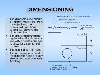
DIMENSIONING • The dimension line should be approximately 3/8” from the object and the extension lines should extend 1/8” beyond the dimension line. • The actual measurement is placed on the dimension line with a break in the line to allow for placement of the text. • The text is also 1/8” high. • The arrows on each end of the dimension line are very slender and approximately 1/8” long.
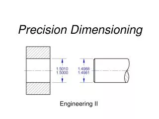
Notation Errors • For fractional inches there is no leading zero before the decimal point. As an example, a quarter of an inch becomes .25 and not 0.25. Avoid inserting a closed quotation mark for an inch measurement such as .25”, and using the notation of “mm” for millimeter measurements such as 68mm.
Continuous Dimensioning • Continuous dimensioning starts on one edge of an object and continues across the object. Unless the object has a finished surface, the dimensions can start on either end or the top or bottom. • Omit one dimension in a series since the overall dimension will provide the missing measurement.
Visibility of Features • Always place dimensions where the shape is most clearly visible. The cuts are more easily seen in the front view. The corners of the cuts in the front view also appear to be formed with “L’s” where lines intersect. • The same cuts, when projected to the top view, appear to form corner intersections with “T’s”. • In order to determine the most visible view, always dimension to the “L’s” and not the “T’s”.
Hidden Lines • Never dimension to a hidden line unless a peculiarity of the object forces the location of an extension line on a hidden line.
Angles • For an angled surface, use either two coordinates or an angle and one coordinate.
Size Dimensions • In order to logically place dimensions, approach the object with the intent of dimensioning in the order of size, location and overall dimensions. • Size dimensions - Start with the smaller parts of the object and work toward the larger and finally the overall dimensions.
Linear Dimension Placement • For very small dimensions, the arrows and text are placed outside the extension lines. As room permits, text is placed between the extension lines and finally the text and arrows. • The last illustration shows a series of small measurements where the “interior” arrows are omitted.
Arc Dimension Placement • For small arcs, omit the center mark and place the arrow and text on the outside of the curve. As the radius increases, the arrow moves inside the curve and the radius is noted with a leader. When the radius is large enough, the measurement also moves inside the curve.
Holes • Holes are represented by a circle in one view and hidden lines in the adjacent views. • The hole is dimensioned where it appears round or circular. The arrow attached to the leader touches the outside of the circle and points to the center of the hole. • Note that the measurement is a diameter by using the symbol of the circle with a slash.
Cylinders • The cylinder is dimensioned where it appears rectangular. Since the cylinder is a complete circle, always provide the diameter and never the radius. • Note that the measurement is a diameter by using the symbol of the circle with a slash.
Locating Rectangular Shapes • Locate the rectangular prism in the top view where two dimensions (height and width) can be used. • Notice that the position of the rectangular prism is more clearly visible in the top view.
Locating Circular Shapes • Location dimensions for circular features such as holes and cylinders are always placed on the object where the hole or cylinder appears round (circular) and not in the view where the hole appears as hidden lines.
Finished Surfaces • The finished surface is important while dimensioning as the linear dimensions typically begin from the finished surface. The finished surface is noted by the finished surface mark (“V”) appearing where the finished surface appears as an edge view.
Slotted Holes • Slotted holes can be dimensioned several different ways. • a. Center points on the longitudinal axis are located and the radii are indicated with a note. • b. Linear measurements indicate the overall size of the slot and the radii are specified. • c. A note indicates the two linear dimensions of the slot and another note specifies the radii. • Choose the most appropriate technique for sizing the slotted hole. The technique used for sizing the slot determines how the slot is located.
Bolt Circle • Holes or cylinders can be located by referencing the diameter of the circle or the radius of the arc. This technique is known as a circle of centers or bolt circle because the holes would typically allow for a bolt to pass through and fasten this part to another. • Slotted holes can be dimensioned several different ways. • a. Center points on the longitudinal axis are located and the radii are indicated with a note. • b. Linear measurements indicate the overall size of the slot and the radii are specified. • c. A note indicates the two linear dimensions of the slot and another note specifies the radii.
Overall Dimensions • After the size and location dimensions have been positioned on the object and necessary notes have been added, the overall dimensions are placed. • The overall dimensions provide the overall height, width, and depth for the object. They are typically placed between the views of the object. Avoid indicating each of the overall dimensions more than once.
Overall Dimensions • Avoid giving an overall measurement for the rounded-end object since a combination of the location dimension and the radius (rounded end) or diameter (cylindrical feature) provides the overall dimension.
Rounded End Objects • The first technique is to provide the location dimension between the center points. The measurements of the radii are given in a note. Omit the overall dimension as location dimension and the radii provide the overall measurement. • The second technique is to provide overall dimensions in the view where the rounded ends appear circular. Since the overall size has been given, the radii are noted with only the “R” to indicate that the ends are formed with a constant radius