Download
1 / 15
170 likes | 530 Vues
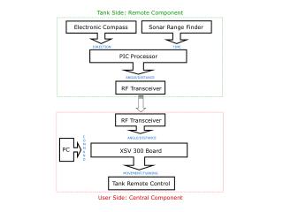
Military University of Technology Warsaw, Poland. Faculty of Electronics Institute of Radioelectronics. Electronic compass design Principles of azimuth measurement and compass operation. Author: Jakub Kazubek Tutor: Lt. Col. Piotr Kaniewski , PhD. Earth’s magnetic field.

E N D
Military University of Technology Warsaw, Poland Faculty of Electronics Institute of Radioelectronics Electronic compass designPrinciples of azimuth measurement and compass operation Author: Jakub Kazubek Tutor: Lt.Col. Piotr Kaniewski, PhD
Earth’s magnetic field • Positions of the magnetic poles do not match the positions of geographic poles • The magnetic poles change their position with time • Earth’s field varies from less than 30µT to over 60µT
The azimuth angle • The direction parallel, to Earth’s surface, component aligns with magnetic S-N direction • The azimuth can be calculated as:
Magnetic field sensorsKMZ51 sensor • The compensation coil allows to compensate the external constant magnetic field • The flipping coil allows to flip internal magnetization vector sense
Sensor offset voltage • Characteristics of the sensor depend on internal magnetization sense (a and b) • The offset voltage does not depend on the internal magnetization direction • The offset voltage depends on supply voltage and can change with time Assuming Earth’s field strength of 15 A/m, supply voltage +5V and maximum temperature differences of 100K: The offset voltage equals: 9mV The voltage caused by the external field is:1,2mV
Offset measurement • Assume a constant external field Hx • Measure Vn voltage • Flip internal magnetization vector • Measure Vp voltage • The offset equals:
Tilt error Transformation between two coordinate systems is needed: Xk Yk Zk =>Xz Yz Zz
Tilt error Tilt error ε depends on: - tilt angle τ - magnetic inclination δ
Tilt correction Horizontal components independent on tilt angle: • Additional elements that have to be measured: • Vertical component Hz – third sensor • Pitch and roll angles – two axis accelerometer
Oscillograms • Voltage across flip coils • Trigger for flip current generator
Electronic compass advantages • No mechanical parts • Digital or analogue (PWM) data output • Possibility of Hard Iron Calibration • Possibility of the True North calibration
Project development • Noise elimination • Implementation of the True North algorithm • Gyro correction • Software development