Download

1 / 9
90 likes | 267 Vues
MAVEN PFDPU P article and F ields D ata P rocessing U nit Mechanical Packaging and Design Overview May 10, 2010. Bill Donakowski UCB/SSL Mechanical Engineer billd@ssl.berkeley.edu. PFDPU Overview/Design Drivers. Box to contain consist of 11 separate cards with frames bolted together

E N D
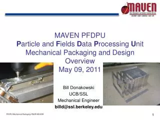
MAVEN PFDPU Particle and Fields Data Processing Unit Mechanical Packaging and Design Overview May 10, 2010 Bill Donakowski UCB/SSL Mechanical Engineer billd@ssl.berkeley.edu
PFDPU Overview/Design Drivers Box to contain consist of 11 separate cards with frames bolted together Each Card contains PCB, connectors, metal frame, EMI shield, and attach fasteners Each card can be removed from Assembly with minimum dis-assembly of box Electrical interconnects as well as external connectors to S/C and individual Instruments Bolted to S/C Panel on one face Frame surface treatment: gold alodined interior, black anodized exterior Box is thermally isolated from S/C Panel High vibe levels: 20.4/14.4 GRMS (Protoflight/Flight)
Cards Stacking 11 Cards: Reg 1, DCB 1, Reg 1, DCB 2, IIB, Sep 1, Sep 2, Mag 1, Mag 2, LPW DFB, LPW BEB 2 Different Card Widths, .700” and 1.15”
Assembly Details 2X Threaded Rod Skewers PC/104 Connector Individual Box Frames (6061 T6 Al) End Shields (6061 T6) Attach Frame (6061 T6) 6 X Attach Feet to S/C S/C Mounting Panel Attach Bolts to Box Frames
Typical Card Layer D-Connector (to S/C or Instrument) Attach Screws Nuts PCB PC104 Interconnect EMI Shield (PCB FR4/Cu) Aluminum Box Frame
Interlocking Frame Overview EMI Shield (.031” thick) PCB (.0625” thick) Frame (.100” thick) Interlocking Features