Download

1 / 39
390 likes | 493 Vues
Frame Relay Option for Service Providers - QoS Mechanisms and SLA. Pre-conference workshop International IT Conference 2002 Colombo, Sri Lanka 4 th October 2002. R. Jayanthan. Bsc.Eng.(Hons), MIEEE, AMIEE, AMIE(SL) MCP, CCNA, NNCDS, NNCAS. Team Leader – Design & Consultancy.

E N D
Frame Relay Option for Service Providers - QoS Mechanisms and SLA Pre-conference workshop International IT Conference 2002 Colombo, Sri Lanka 4th October 2002 R. Jayanthan. Bsc.Eng.(Hons), MIEEE, AMIEE, AMIE(SL) MCP, CCNA, NNCDS, NNCAS Team Leader – Design & Consultancy jayan@iee.org
Objectives • At the end of this workshop you will be able to: • Define how Frame Relay defers from other communication technology • Describe the features & benefits of Frame Relay technology • Explain the Quality of Service mechanism built-in to Frame Relay technology • Discuss the Service Level Agreement Parameters and Measurements related to Frame Relay
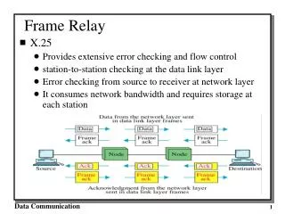
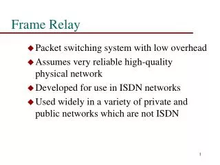
What is not Frame Relay ? • Frame Relay is not a networking protocol ! • Frame Relay • Is an Interface Protocol used in wide area networking • Frame Relay User - Network Interface (UNI) • Frame Relay Network - Network Interface (NNI)
Frame Relay Interfaces Frame Relay Network Frame Relay Network CPE FR-NNI FR-UNI CPE FR-UNI UNI – Between Customer and Operator NNI – Between two Operators
Leased Line based Network Router Router Router Router Multiple Interfaces, DSU/CSUs and Links Router
Leased Line based Network • Advantages • Simple • Totally Managed by the Customer organization • The links are ‘private’ to the organization • Considered to be secure • Disadvantages • Not optimum in bandwidth utilization • High number of links & physical ports required. • Hence expensive to the customer • Confined to LAN traffic (IP/IPX) • Does not provide extensive QoS features
Frame Relay based Network Virtual Circuits FRAD DTE FRAD DTE Frame Relay Switch DCE Frame Relay Switch DCE Single Physical Link Frame Relay Switch DCE Frame Relay Switch DCE FRAD DTE FRAD DTE Frame Relay Switch DCE Frame Relay UNI FRAD DTE
A Shared Network Access Link Frame Relay Switch DCE Frame Relay Switch DCE Frame Relay Switch DCE Frame Relay Switch DCE Frame Relay Switch DCE Network Trunk Link
Frame Relay based Network • Network bandwidth is shared • Single physical port at CPE • Virtual Circuits are configured through software • Built-in QoS mechanism • Less frame overhead hence fast switching • Support for switched virtual circuit enables on-demand services viz. voice & video calls
TDM vs. Frame Relay TDM Approach Virtual Circuit Approach
Types of Virtual Circuits SVC • Permanent Virtual Circuits • Switch Virtual Circuits CPE LAN CPE PVC LAN CPE LAN
FR-UNI Physical Link Permanent Virtual Circuits PVC Frame Relay Switch DCE
DLCI • Data Link Control Identifier • Identifies each PVC within a FR-UNI Frame Relay Switch DCE DLCI 16 Router DTE DLCI 17 DLCI 18 DLCI 19 Frame Relay Network FR-UNI
DLCI (Cont…) • Assigned unique to each logical channel (PVC) within one FR-UNI • DLCI has only local significance • DLCI values has to be provided by the Network Operator • Can be from 16 to 1023 in value • (DLCI 0 - 15 are reserved)
Frame Relay Frame Structure 2 bytes Variable byte 2 bytes 1 byte 1 byte Flag Header I field FCS Flag DLCI DLCI LAPF Frame C/R BECN DE EA EA FECN 8 7 6 5 4 3 2 1 8 7 6 5 4 3 2 1 • C/R Command /Response • EA Address Extension • FECN Forward Explicit Congestion Notification • BECN Backward Explicit Congestion Notification • DE Discard Eligible Frame Relay supports 2, 3 or 4 byte headers resulting in more DLCI’s per FR-UNI. However 2 byte header is the most commonly implemented.
Need for Congestion Management Subscriber Output buffer Frame Handler Input buffer Switch Node
Congestion Management Severe congestion Mild congestion No congestion Delay Throughput or Delay Throughput Offered Load ITU Recommendation I.370 defines the frame relay congestion
Congestion Control Techniques • Discard Strategy • Providing guidance to the network regarding which frames to discard; by way of CIR and DE bit. • Congestion Avoidance • Providing guidance to the end systems about the congestion in the network; by way of FECN, BECN and CLLM. This is called explicit control. • Congestion Recovery • End system infers congestion from frame loss; by way of higher level protocol function. This is called implicit control.
FECN / BECN Server User data FECN=1 / BECN=0 Congestion User data FECN=0 / BECN=0 Frame Relay Network User data FECN=0 / BECN=0 User data FECN=0 / BECN=1 Congestion in the direction of Server The end stations (or Transport protocol such as TCP) shall take care of FECN/BECN to avoid congestion Client
CLLM Message • Consolidated Link Layer Management message • Is a variation of BECN • Used when no reverse traffic is available • Carries congestion information of multiple virtual circuits
Implicit Control • When a higher layer protocol detects frame discards, it can adapt rate control such as using sliding window technique. • This function is independent of Frame Relay technology and usually handled by transport layer protocol like TCP.
Service Parameter Definition • CIR - • Tc - • Bc - • Be - Committed Information Rate: The guaranteed throughput provided by the network for the user traffic under normal operation Committed Rate Measurement Interval or Bandwidth Interval Committed Burst Size: The maximum amount of data the network agrees to transfer, under normal conditions, over the measurement interval of Tc Excess Burst Size: The maximum amount of data in excess of Bc the network will attempt to transfer, over a period of Tc Bc + Be # of Bits Transmitted Access Rate Bc CIR Time Tc
Example Service Parameters Access Rate = 2.048 Mbps Tc = 1.125 s CIR = 128 kbps Permits a burst rate Bc = 144 kbps • These parameters are defined per virtual circuit • Though the CIR is 128 kbps, user data is fed in to the network at 2.048 Mbps resulting in low latency; 15 times faster in this example. • A single physical link can carry several virtual circuits and the service parameters are configured according to the: • Type of traffic, viz. real-time, transaction, database backup & replication, etc. • Bandwidth required
Discard Eligible (DE) bit • DE=0: The frame is guaranteed to be delivered. • DE=1: The frame delivered if possible The DE bit is used to mark a frame as Discard Eligible at the ingress port of the Frame Relay switch first Frame Relay switch if the input data rate exceed the committed burst rate CPE FR Switch FR Switch DE=1 Egress Port Ingress port CPE Frame Relay Network
Traffic Management using CIR and DE bit # of Bits Transmitted Bc + Be Access Rate Bc CIR Tc Time Frame 1 DE = 0 Frame 3 DE = 1 Frame 2 DE = 0 Frame 4 Discarded
CIR Gauge Current Rate CIR Maximum Rate Transmission if possible Guaranteed transmission Discard all excess Access Rate 0
Leaky Bucket Algorithm Input data Limit C = Bc+Be Discard any incoming data while C is at its threshold Be (set DE=1 and forward) C C = Counter; increases with incoming data Bc Decrement C by MIN [C, Bc] every Tc time units Bc CIR = ----- Tc
Service Level Agreement • Compare different service providers • Measure the quality of specific service • Enforce contractual commitments Frame Relay service offerings are available from multiple service providers. Each provider describes the offering by specifying user information transfer parameters. End-users of the service utilize these parameters to:
FRF.13 Implementation Agreement • Frame Relay Forum Implementation Agreement FRF.13 specifies the SLA parameters that describes frame service performance • Frame Transfer Delay (FTD) • The time required to transfer data through the network • Frame Delivery Ratio (FDR,FDRc, FRDe) • Effectiveness in transporting offered load in one direction in a single virtual circuit • Data Delivery Ratio (DDR, DDRc, DDRe) • Effectiveness in transporting payload • Service Availability (FRVCA, FRMTTR, FRMTBSO)
FRF.13 Connection Components Frame Relay Network Frame Relay Network Frame Relay Network Internetwork Circuit Section Internetwork Circuit Section Access Circuit Section Access Network Section Transit Network Section Access Network Section Access Circuit Section FR-DTE FR-DTE FR-NNII FR-UNI FR-UNI FR-NNI
FRF.13 Reference Points Intermediate Nodes SrcRP SourceFR-DTE (Optional) Measurement Function Frame Relay End System EqiRP EqoRP TpRP Egress Queue Function L1/L2 Function Traffic Policing Function Egress Node Ingress Node Public Frame Relay Network IngRP (Optional) Measurement Function Destination FR-DTE Frame Relay End System DesRP
FRF.13 Scopes End-to-end Scope Edge-to-edge Interface Scope Edge-to-edge Queue Scope Public Frame Relay Network (s) FR-DTE FR-DTE FR-UNI FR-UNI Private FR Network FR-UNI FR-UNI / NNI
Delay Frame Transfer Delay FTD = t2 – t1 t1 – time when the frame left the source (ms) t2 – time the frame arrived at the destination (ms)
Frame Delivery Ratio (FDR) (FramesDeliveredc + FramesDeliverede) (FramesOfferedc + FramesOfferede) FDR = = FDRc = FDRe = (FramesDeliveredc+e) (FramesOfferedc+e) (FramesDeliveredc) (FramesOfferedc) [FDR for load consisting of frames within CIR] (FramesDeliverede) (FramesOfferede) [FDR for load in excess of CIR]
Data Delivery Ratio (DDR) (DataDeliveredc + DataDeliverede) (DataOfferedc + DataOfferede) DDR = = DDRc = DDRe = (DataDeliveredc+e) (DataOfferedc+e) (DataDeliveredc) (DataOfferedc) [FDR for load consisting of frames within CIR] (DataDeliverede) (DataOfferede) [FDR for load in excess of CIR] Data = Frame – Header - FCS
Service Availability Frame Relay virtual connection availability IntervalTime - ExcludedOutageTime – OutageTime IntervalTime - ExcludedOutageTime FRVCA = * 100 Frame Relay mean time to repair for virtual connection when OutageCount > 0 OutageTime OutageCount FRMTTR = Frame Relay mean time between service outage for virtual connection when OutageCount > 0 IntervalTime – ExcludedOutageTime – OutageTime OutageCount FRMTBSO = When OutageCount = 0, then FRMTTR = 0 and FRMTBSO = 0
Summary • Frame Relay standards only define Interface Protocols. • It enables network sharing and bandwidth optimization. • The Frame Relay UNI & NNI have traffic management And congestion control mechanisms built-in. • SLA parameters are defined to measure the network performance on a per virtual circuit basis.
Reference • Further reading: • Uyless Black: Frame Relay Networks, McGraw-Hill, 1998 • William Stallings: ISDN and Broadband ISDN with Frame Relay and ATM, Prentice Hall, 2000 • Configuring Frame Relay Services: BayRS documentation- WAN Suite Protocols. • Nortel MAGELAN Training Manual: Network Engineering Volume 1 & 2 • Frame Relay Forum web site www.frforum.com