Frame Relay
Frame Relay. Muhammad Wasif Laeeq Roll # : BSIT07-01. OSI Reference Model. Frame Relay. Application. Presentation. Session. Transport. Network. IP/IPX/AppleTalk, etc. Data Link. Frame Relay. EIA/TIA-232, EIA/TIA-449, V.35, X.21, EIA/TIA-530. Physical. Types of Switched Networks.


Frame Relay
E N D
Presentation Transcript
Frame Relay Muhammad Wasif Laeeq Roll # : BSIT07-01
OSI Reference Model Frame Relay Application Presentation Session Transport Network IP/IPX/AppleTalk, etc. Data Link Frame Relay EIA/TIA-232, EIA/TIA-449, V.35, X.21, EIA/TIA-530 Physical
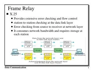
Circuit Switched Networks • A circuit Switched Network is made of a set of switches connected by physical links • Resources are Reserved… Packet Switched Networks • No Resources Reservation • Resources are allocated on Demand
Virtual Circuit Network • Resources can be allocated during setup (PVC) • Resources can be allocated on demand (SVC)
Addressing • Global Addressing • Local Addressing
Global Addressing • Source and destination has a global address • Global address is Unique • Global address are used to create local addresses (VCI)
Virtual Circuit Identifier • VCI is local address • Used for data transfer • VCI in Frame relay Network is called DLCI (Data Link Connection Identifier)
Data-Link Connection Identifier (DLCI) • Frame Relay virtual circuits are identified by data-link connection identifiers (DLCIs). DLCI values typically are assigned by the Frame Relay service provider (for example, the telephone company). • Frame Relay DLCIs have local significance, which means that their values are unique in the LAN, but not necessarily in the Frame Relay WAN.
CSU/DSU Frame Relay, Address Mapping PVC 10.1.1.1 DLCI: 500 Inverse ARP orFrame Relay map FrameRelay IP(10.1.1.1) DLCI (500)
Frame Relay Virtual Circuits • PVS’s (Permanent Virtual Circuit) • SVC’s (Switched Virtual Circuit)
Switched Virtual Circuits (SVCs) • Switched virtual circuits (SVCs) are temporary connections used in situations requiring only sporadic data transfer between DTE devices across the Frame Relay network. A communication session across an SVC consists of the following four operational states: • Call setup—The virtual circuit between two Frame Relay DTE devices is established. • Data transfer—Data is transmitted between the DTE devices over the virtual circuit. • Idle—The connection between DTE devices is still active, but no data is transferred. If an SVC remains in an idle state for a defined period of time, the call can be terminated. • Call termination—The virtual circuit between DTE devices is terminated.
Permanent Virtual Circuits (PVCs) • Permanent virtual circuits (PVCs) are permanently established connections that are used for frequent and consistent data transfers between DTE devices across the Frame Relay network. Communication across a PVC does not require the call setup and termination states that are used with SVCs. PVCs always operate in one of the following two operational states: • Data transfer—Data is transmitted between the DTE devices over the virtual circuit. • Idle—The connection between DTE devices is active, but no data is transferred. Unlike SVCs, PVCs will not be terminated under any circumstances when in an idle state. • DTE devices can begin transferring data whenever they are ready because the circuit is permanently established.
Frame Relay Muhammad Aatif Aneeq Roll # : BSIT07-15
Frame Relay Frame Formats • Flags—Delimits the beginning and end of the frame. The value of this field is always the same and is represented either as the hexadecimal number 7E or as the binary number 01111110.
Frame Relay Frame Formats Address—Contains the following information: (in bits) • DLCI—The 10-bit DLCI is the essence of the Frame Relay header. This value represents the virtual connection between the DTE device and the switch. Each virtual connection that is multiplexed onto the physical channel will be represented by a unique DLCI. The DLCI values have local significance only, which means that they are unique only to the physical channel on which they reside. Therefore, devices at opposite ends of a connection can use different DLCI values to refer to the same virtual connection.
Frame Relay Frame Formats • Extended Address (EA)—The EA is used to indicate whether the byte in which the EA value is 1 is the last addressing field. If the value is 1, then the current byte is determined to be the last DLCI octet. Although current Frame Relay implementations all use a two-octet DLCI, this capability does allow longer DLCIs to be used in the future. The eighth bit of each byte of the Address field is used to indicate the EA.
Frame Relay Frame Format • C/R—The C/R is the bit that follows the most significant DLCI byte in the Address field. The • C/R bit is not currently defined.
Congestion Control • Last 3 bits in address field • FECN • BECN • DE
Forward-explicit congestion notification • FECNis a single-bit field that can be set to a value of 1 by a switch to indicate to an end DTE device, such as a router, that congestion was experienced in the direction of the frame transmission from source to destination. The primary benefit of the use of the FECN and BECN fields is the capability of higher-layer protocols to react intelligently to these congestion indicators. Today, DEC net and OSI are the only higher-layer protocols that implement these capabilities.
Backward-explicit congestion notification • BECNis a single-bit field that, when set to a value of 1 by a switch, indicates that congestion was experienced in the network in the direction opposite of the frame transmission from source to destination.
Discard eligibility • (DE) is set by the DTE device, such as a router, to indicate that the marked frame is of lesser importance relative to other frames being transmitted. Frames that are marked as “discard eligible” should be discarded before other frames in a congested network. This allows for a basic prioritization mechanism in Frame Relay networks.
Frame Relay Frame Format • Data—Contains encapsulated upper-layer data. Each frame in this variable-length field includes a user data or payload field that will vary in length up to 16,000 octets. This field serves to transport the higher-layer protocol packet (PDU) through a Frame Relay network. • Frame Check Sequence—Ensures the integrity of transmitted data. This value is computed by the source device and verified by the receiver to ensure integrity of transmission.
FRAD Frame Relay Assembler Dissembler