Frame Relay
Frame Relay. W.lilakiatsakun. Introduction (1). Frame Relay is a high-performance WAN protocol that operates at the physical and Data Link layers of the OSI reference model. a simpler version of the X.25 protocol


Frame Relay
E N D
Presentation Transcript
Frame Relay W.lilakiatsakun
Introduction (1) • Frame Relay is a high-performance WAN protocol that operates at the physical and Data Link layers of the OSI reference model. • a simpler version of the X.25 protocol • Network providers commonly implement Frame Relay for voice and data as an encapsulation technique, used between LANs over a WAN.
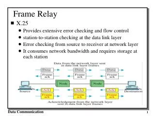
Introduction to Frame Relay (1) • Frame Relay has lower overhead than X.25 because it has fewer capabilities. • Frame Relay does not provide error correction, modern WAN facilities offer more reliable connection services and a higher degree of reliability than older facilities. • The Frame Relay node simply drops packets without notification when it detects errors.
Introduction to Frame Relay (2) • Frame Relay handles volume and speed efficiently by combining the necessary functions of the data link and Network layers into one simple protocol. • As a data link protocol, Frame Relay provides access to a network, delimits and delivers frames in proper order, and recognizes transmission errors through a standard Cyclic Redundancy Check.
Introduction to Frame Relay (3) • As a network protocol, Frame Relay provides multiple logical connections over a single physical circuit and allows the network to route data over those connections to its intended destinations.
Frame Relay Operation (1) • The connection between a DTE device and a DCE device consists of both a Physical layer component and a link layer component: • The physical component defines the mechanical, electrical, functional, and procedural specifications for the connection between the devices.
Frame Relay Operation (2) • The link layer component defines the protocol that establishes the connection between the DTE device, such as a router, and the DCE device, such as a switch. • Frame Relay access device (FRAD) is known as the DTE. • The FRAD is sometimes referred to as a Frame Relay assembler/dissembler and is a dedicated appliance or a router configured to support Frame Relay.
Virtual Circuit (1) • The connection through a Frame Relay network between two DTEs is called a virtual circuit (VC). • The connection is logical, and data moves from end to end, without a direct electrical circuit. • With VCs, Frame Relay shares the bandwidth among multiple users
Virtual Circuit (3) • There are two ways to establish VCs: • SVCs, switched virtual circuits, are established dynamically by sending signaling messages to the network (CALL SETUP, DATA TRANSFER, IDLE, CALL TERMINATION). • PVCs, permanent virtual circuits, are preconfigured by the carrier, and after they are set up, only operate in DATA TRANSFER and IDLE modes. • Note that some publications refer to PVCs as private VCs.
Frame Relay DLCIs (1) • Frame Relay DLCIs (Data Link Connection Identifier) • They have local significance, which means that the values themselves are not unique in the Frame Relay WAN. • A DLCI identifies a VC to the equipment at an endpoint. • Two devices connected by a VC may use a different DLCI value to refer to the same connection.
Multiple VC (1) • Frame Relay is statistically multiplexed, meaning that it transmits only one frame at a time, but that many logical connections can co-exist on a single physical line. • This capability often reduces the equipment and network complexity required to connect multiple devices, making it a very cost-effective replacement for a mesh of access lines
Frame Relay Encapsulation (3) • DLCI • The 10-bit DLCI is the essence of the Frame Relay header. • This value represents the virtual connection between the DTE device and the switch. • Each virtual connection that is multiplexed onto the physical channel is represented by a unique DLCI.
Frame Relay Encapsulation (4) • Extended Address (EA) • If the value of the EA field is 1, the current byte is determined to be the last DLCI octet. • Although current Frame Relay implementations all use a two-octet DLCI, this capability does allow longer DLCIs in the future. • The eighth bit of each byte of the Address field indicates the EA.
Frame Relay Encapsulation (5) • C/R (Command/Response) • The bit that follows the most significant DLCI byte in the Address field. • The C/R bit is not currently defined. • Congestion Control ( The FECN, BECN, and DE bits ) contains 3 bits that control the Frame Relay congestion-notification mechanisms.
Frame Relay Topology (1) • Star Topology (Hub and Spoke) • A Company has a central site that acts as a hub and hosts the primary services. • the location of the hub is usually chosen by the lowest leased-line cost • Connections to each of the remote sites act as spokes. • each remote site has an access link to the Frame Relay cloud with a single VC.
Frame Relay Topology (4) • Full Mesh Topology • A full mesh topology suits a situation in which the services to be accessed are geographically dispersed and highly reliable access to them is required. • A full mesh topology connects every site to every other site.
Frame Relay Topology (7) • Partial Mesh Topology • With partial mesh, there are more interconnections than required for a star arrangement, but not as many as for a full mesh. • The actual pattern is dependant on the data flow requirements.
Frame Relay Address Mapping (1) • Inverse ARP (The Inverse Address Resolution Protocol) • To obtain Layer 3 addresses of other stations from Layer 2 addresses, such as the DLCI in Frame Relay networks. • It is primarily used in Frame Relay and ATM networks.
Frame Relay Address Mapping (2) • Dynamic Mapping • The Frame Relay router sends out Inverse ARP requests on its PVC to discover the protocol address of the remote device. • The router uses the responses to populate an address-to-DLCI mapping table on the Frame Relay router or access server.
Frame Relay Address Mapping (3) • Static Mapping • The user can choose to override dynamic Inverse ARP mapping by supplying a manual static mapping for the next hop protocol address to a local DLCI. • You cannot use Inverse ARP and a map statement for the same DLCI and protocol.
LMI (Local Management Interface) (1) • The LMI is a keepalive mechanism that provides status information about Frame Relay connections between the router (DTE) and the Frame Relay switch (DCE). • Every 10 seconds or so, the end device polls the network, either requesting a dumb sequenced response or channel status information.
LMI (Local Management Interface) (2) • If the network does not respond with the requested information, the user device may consider the connection to be down. • When the network responds with a FULL STATUS response, it includes status information about DLCIs that are allocated to that line. • The end device can use this information to determine whether the logical connections are able to pass data.
LMI (Local Management Interface) (4) • LMI Extensions (1) • VC status messages • Provide information about PVC integrity by communicating and synchronizing between devices, periodically reporting the existence of new PVCs and the deletion of already existing PVCs. • VC status messages prevent data from being sent into black holes (PVCs that no longer exist).
LMI (Local Management Interface) (5) • LMI Extensions (2) • Multicasting • Allows a sender to transmit a single frame that is delivered to multiple recipients. • Multicasting supports the efficient delivery of routing protocol messages and address resolution procedures that are typically sent to many destinations simultaneously.
LMI (Local Management Interface) (6) • LMI Extensions (3) • Global addressing • Gives connection identifiers global rather than local significance, allowing them to be used to identify a specific interface to the Frame Relay network. • Global addressing makes the Frame Relay network resemble a LAN in terms of addressing, and ARPs perform exactly as they do over a LAN.
LMI (Local Management Interface) (7) • LMI Extensions (4) • Simple flow control • Provides for an XON/XOFF flow control mechanism that applies to the entire Frame Relay interface. • It is intended for those devices whose higher layers cannot use the congestion notification bits and need some level of flow control