Frame Relay
Frame Relay. Raj Jain Professor of Computer and Information Sciences The Ohio State University Columbus, OH 43210 jain@acm.org These slides are available at http://www.cse.ohio-state.edu/~jain/cis777-00/. Overview. What is Frame Relay? Why not leased lines or X.25?

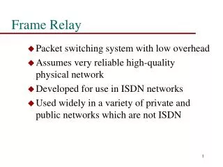
Frame Relay
E N D
Presentation Transcript
Frame Relay Raj Jain Professor of Computer and Information SciencesThe Ohio State UniversityColumbus, OH 43210 jain@acm.org These slides are available athttp://www.cse.ohio-state.edu/~jain/cis777-00/
Overview • What is Frame Relay? • Why not leased lines or X.25? • Frame formats and protocols • Signaling
Problems with Leased Lines • Multiple logical links Multiple connections • Four nodes 12 ports, 12 local exchange carrier (LEC) access lines, 6 inter-exchange carrier (IXC) connections • One more node 8 more ports, 8 more LEC lines, 4 more IXC circuits Router Router LEC IXC Router Router
Solution: X.25/Frame Relay • Four nodes: 4 ports, 4 LEC access lines, 6 IXC circuits • One more node: 1 more port, 1 more access line, 4 more IXC circuits • Share leased lines Virtual Private Networks Router Router LEC IXC Router Router
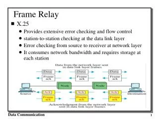
X.25 • In-band signaling. VC setup and clearing messages in the same channel as data. • Three layer protocol. Third layer for multiplexing. • Flow control • Error control 16 messages for one packet transfer Only 8 messages without flow control and error control
X.25 Exchange DCE DCE 12 14 3 5 4 6 DTE DTE 11 16 2 15 1 9 8 7 10 Source Destination
Frame Relay Exchange 2 3 7 6 8 1 5 4 Source Destination
Frame Relay: Key Features • X.25 simplified • No flow and error control • Out-of-band signaling • Two layers • Protocol multiplexing in the second layer • Congestion control added Higher speed possible.X.25 suitable to 200 kbps. Frame relay to 2.048 Mbps.
Relay vs Switching • Switching = Relaying + Ack + Flow control + Error recovery + loss recovery • Switching = X.25 • Relay = Unreliable multiplexing service
Datalink Control Identifiers • DLCI: Similar to Logical Channel Numbers in X.25 Router Router 1 1 2 FR 2 FR 3 FR 1 Router Router
Data Link Control Identifier • Only local significance • Allows multiple logical connections over one circuit • Some ranges preassigned • DLCI = 0 is used for signaling
ISDN Reference Model Management Control User 7 6 5 4 3 2 1
Control User Network Q.931/Q.933 User Selectable LAPDQ.921/Q.922 LAPF Q.922 Core I.430/I.431 Physical Frame Relay UNI Architecture • UNI = User-network Interface • LAPF = Link Access Protocol - Frame Mode Services • LAPD = Link Access Protocol - D Channel
Control Plane • Signaling over D channel (D = Delta = Signaling) • Data transfer over B, D, or H (B = Bearer) • LAPD used for reliable signaling • ISDN Signaling Q.933 + Q.931 used for signaling messages • Service Access Point Identifier (SAPI) in LAPD = 0 Q.933 + Q.931 Frame relay message
User Plane • Link Access Procedure for Frame-Mode bearer services (LAPF) • Q.922 = Enhanced LAPD (Q.921) = LAPD + Congestion • LAPF defined in Q.922 • Core functions defined in Q.922 appendix: • Frame delimiting, alignment, and flag transparency • Virtual circuit multiplexing and demultiplexing • Octet alignment Integer number of octets before zero-bit insertion • Checking min and max frame sizes
NetworkLayer NetworkLayer LAPFControl LAPFControl LAPF Core LAPF Core LAPF Core LAPF Core I.430/I.431 I.430/I.431 I.430/I.431 I.430/I.431 User Plane (Cont) • Error detection, Sequence and non-duplication • Congestion control • LAPF control may be used for end-to-end signaling
Flag01111110 Address Information FCS Flag01111110 1B 2-4B 2B 2B LAPF-Core Frame Format • LAPF is similar to LAPD: Flag, bit stuffing, FCS • No control frames in LAPF-Core No control field • No inband signaling • No flow control, no error control, no sequence numbers • Logical Link Control (LLC) may be used on the top of LAPF core
8 7 6 5 4 3 2 1 Upper DLCI C/R EA 0 Lower DLCI FECN BECN DE EA 1 LAPF Address Field • 2 Octet: Upper DLCI C/R EA 0 • 3 Octet: DLCI FECN BECN DE EA 0 Lower DLCI or DL-Core control D/C EA 1 Upper DLCI C/R EA 0 • 4 Octet: DLCI FECN BECN DE EA 0 DLCI EA 0 Lower DLCI or DL-Core control D/C EA 1
LAPF Address Field • Address length = 2, 3, or 4 bytes • Data Link Control Identifier (DLCI) = 10, 16, 17, or 23 bits • Address Extension (EA) bits: 0 More bytes • D/C = Remaining bits for DLCI or for core control protocol (No use for core control has been defined) • C/R = Command/response (not used) • FECN = Forward Explicit Congestion Indication • BECN = Backward Explicit Congestion Indication
Local Management Interface (LMI) • Extension designed by a group of vendors • To overcome problems observed in early implementations • May be standardized by both ANSI and ITU-T • Status Enquiry (SE) message from user to network • Status (S) message from network to user • Uses HDLC UI frames (with sequence numbers) • Uses protocol ID=00001001, DLCI=1023
LMI Operation User Network SE, S = 4, R = 3 S, S = 3, R = 5 SE FS (All PVCs) SE S (New PVCs)
DLCI Extensions • Global DLCI DLCI points to the same destination at all time and points (OK for small networks) • Multicasting • One-way multicasting: 1 to N • Two-way multicasting: 1 to N and N to 1 • N-way Multicasting: N to N
FrameRelayNet A FrameRelayNet B FrameRelayNet C User User SE SE SE SE S S S S Network-to-Network Interface (NNI) • Developed by frame relay forum: FRF 92.08R1, FRF 92.62 • Working draft of ANSI T1S1.2 • Adding/deleting PVCs between networks • Diagnosing PVC failures
Major NNI Operations • Notification of adding a PVC • Notification of deleting a PVC • Notification of UNI or NNI failures • Notification of a PVC segment availability or unavailability • Verification of links between frame relay nodes • Verification of frame relay nodes
Summary • X.25 designed for unintelligent devices over error-prone networks Slow • Frame relay = Simplified X.25 • Higher data rates than X.25 • Developed for ISDN but runs in non-ISDN environments • Two layer protocol architecture
Homework • Read Section 7.2 of McDysan’s book
Additional References • Chapter 11 of Stallings’ “ISDN and Broadband ISDN with Frame Relay and ATM” • P. Smith, “Frame Relay: Principles and Applications,” Addison-Wesley, 1993. • U. Black, “Frame Relay Networks,” 2nd Ed., McGraw-Hill, 1995 • C. A. Heckart, “The Guide to Frame Relay Networking,” Flatiron Publishing, 1994 • Frame Relay Forum, http://www.frforum.com