Download
1 / 11
130 likes | 521 Vues
Axial Members. AXIAL MEMBERS, which support load only along their primary axis, are the most basic of structural members. Equilibrium requires that forces in Axial Members are always Equal, Opposite, and Co-Linear. In most cases, axial members have pinned ends.

E N D
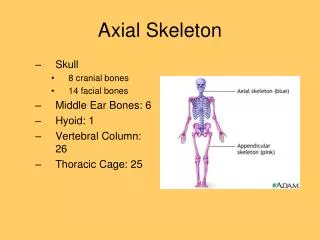
Axial Members • AXIAL MEMBERS, which support load only along their primary axis, are the most basic of structural members. • Equilibrium requires that forces in Axial Members are always Equal, Opposite, and Co-Linear. • In most cases, axial members have pinned ends. • Some examples of axial members include: • Bars; • Truss Members; • Ropes and Cables.
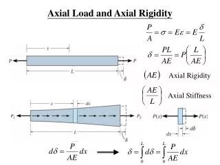
Axial Stress • If a cut is taken perpendicular to a bar's axis, exposing an internal cross-section of area A, the force per unit area on the face of this cut is termed STRESS. • The symbol used for normal or axial stress in most engineering texts is s (sigma). • Stress in an axially loaded bar is: • s = F/A • Stress is positive in tension (P>0) and negative in compression (P<0); • English units: psi (pounds per square inch), or ksi (kilopounds per square inch);
Axial Stress • The axial stress of a member is determined by: • = F / A Where F = force applied along the longitudinal axis of the member perpendicular to the cross sectional area (A).
Axial Stress Example • A cylindrical steel bar has a diameter of ½” • The bar is attached at one end and a 5,000 lb weight is hung from the steel bar (axially loaded) • What is the axial stress generated in the bar? • Area of a circle = p r2 • s = F/A =5,000 lb/.20 in 2 =25,000 psi
Axial Strain • An axial bar of length L, and cross-sectional area A, subjected to tensile force F, elongates by an amount, D. • The change in length divided by the initial length is termed ENGINEERING STRAIN (or simply strain). • Strain is positive in tension and negative in compression • Strain is a non-dimensional length - a fraction. • Because strain is small, it is often given as a percentage by multiplying by 100%: e.g., e = 0.003 = 0.3%.
Axial strain is a measure of the deformation to a member due to axial stress. e = d / L Where: e represents axial strain d representsthe change in length L represents the original length Axial Strain
Young's Modulus • Recall that all materials have a stiffness associated with them. • The stiffness of a material is defined through the relation: s = E e or E = s / e • Where: E is the YOUNG'S MODULUS or stiffness of the material. e is the axial strain s is the axial stress • Values of E for different materials are obtained experimentally from stress-strain curves.
Axial Strain Example • In the previous example, a cylindrical steel bar has a diameter of ½” and a 5,000 lb weight is hung from the end (axially loaded) • Young’s Modulus for steel is 29,000,000 psi • We found the axial stress to be 25,000 psi • What is the expected strain? • s = E e or E = s / e or e = s/E • Where: • E is the YOUNG'S MODULUS or stiffness of the material. • e is the axial strain • s is the axial stress • e = (25,000 psi)/(29,000,000 psi) = .00086 or .086%
Axial Strain Example (Cont.) • If the steel bar were 10 feet in length, what would the change in length be when axially loaded? • e = d / L • Where: • e represents axial strain • d represents the change in length (deformation) • L represents the original length • .00086 = d / 10 feet • .0086 feet
Using Young’s Modulus, we can determine the expected deformation of a member due to a constant force being applied. Where: d = Change in length F = Force applied L = Original length of member A = Cross sectional area E = Young’s Modulus Expected Deformation
Expected Deformation • Using the Stress and Strain formulas, we found the 10 foot steel rod is expected to change length by .0086 feet when axially loaded with 5,000 pounds • Using the expected deformation formula, we also find: • d = FL/AE • =(5,000 lbs)(10 ft)/(.20 in2)(29,000,000 psi) = .0086 feet