Download
1 / 1
70 likes | 377 Vues
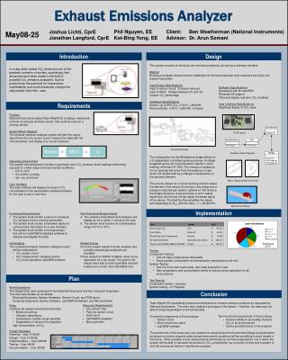
Exhaust Emissions Analyzer. Phil Nguyen, EE Ket-Bing Yong, EE. Client: Ben Weatherman (National Instruments) Advisor: Dr. Arun Somani. Joshua Lichti, CprE Jonathan Langford, CprE. May08-25. Design. Introduction.

E N D
Exhaust Emissions Analyzer Phil Nguyen, EE Ket-Bing Yong, EE Client: Ben Weatherman (National Instruments) Advisor: Dr. Arun Somani Joshua Lichti, CprE Jonathan Langford, CprE May08-25 Design Introduction The system consists of electrical and mechanical aspects, as well as a software interface. Method Building a compact exhaust sensor challenges for the team because most analyzers are bulky and require high power. Input/Output Specifications Input to sensor circuit: Emission exhaust Input to MCU: Voltage between 0V and 5V Output: CO2 percentage Hardware Specifications Sensor: up to 50% CO2, 0-50°C, <200mW Microcontroller: 0-50°C, <200mW, >2 inputs In a day when global CO2 levels are one of the greatest concerns of society, surprisingly few advances have been made in the field of portable CO2 emission analyzers. Such a product has the potential for tremendous marketability and could drastically change the way people view their cars. Software Specifications Developed with NI LabVIEW Windows OS support Filter and display real-time CO2 readings User Interface Specifications Graphical display of CO2 value Requirements • Problem • National Instruments asked Team May08-25 to design, implement, • and test an exhaust emission sensor that could be used on a • moving vehicle. • System Block Diagram • The exhaust emission analyzer system will take the output • signal from the CO2 sensor circuit, interpret the data with the • microcontroller, and display it on a user interface. • Operating Environment • The system was designed to be able to generate valid, CO2 emission-level readings while being exposed to a wide range of environmental conditions: • 0°C to 70°C • 0% to 80% humidity • rain, ice, and snow • User Interface • The user interface will display the level of CO2 • concentration in the automobile’s exhaust emission • for the user to see in real time. PCB Layout Circuit Schematic Software Class Diagram The configuration for the Wheatstone bridge allows for a 2 independent controlled sensing scheme. A voltage is applied across pin 6 and 22 which results in Joule heating of Element #1 (R3). The change in resistance for our purpose will come from the presence of gas which will exhibit itself as a change in temperature to the exposed Element. The circuitry allows for a 2 pixel sensing scheme where the filament of the sensor is one leg of the bridge and a precision matched pair resistor network of 10K ohms is the bridge reference. A set point bias is set to adjust signal size, but the use of high signal increases aging of the device. The final Op Amp amplifies the signal with depending on R16, with the Gain = 1 + 49.9K/R16. Mirror Stand and Mirror Holder Mechanical Design • Functional Requirements • The system shall contain a sensor to measure CO2 emission from a moving automobile. • The system shall contain a hardware device to communicate information to a user interface. • The system shall contain a microprocessor that will run LabVIEW Embedded software to interpret and display the data. • Deliverables • The completed exhaust emission analyzer project will be composed of: • CO2 sensor circuit • CO2 measurement hardware device • CO2 level calculation LabVIEW software • Non-Functional Requirements • The software shall detect lost hardware and display an error within 1 minute of the loss. • The system shall function at a temperature range of 0°C to 70°C. • Market Survey • From the market research found, wireless and portable exhaust gas analyzers are available. • Prices range from $4000 to $5000, which is too expensive for a car owner. The goal of the design team was to build a portable exhaust analyzer at a much more affordable cost. Implementation Total Hours 603.5 • Testing • Component Testing • Test all major components individually • Ensure power consumption and temperature specifications are met • System Testing • Test full circuit with multi-meter, then Data Acquisition Card • Vary temperature and concentration levels to ensure correct operation for all environments. • Test Results • Component testing – Success • System testing – In Progress Plan • Work Breakdown • The design team was composed of two Electrical Engineers and two Computer Engineers. • The work was divided up as follows: • Electrical Engineers: System Hardware, Sensor Circuit, and PCB layout • Computer Engineers: System Software, LabVIEW Embedded, and Microcontroller Conclusion • Team May08-25 successfully planned and designed an exhaust emission analyzer as requested by National Instruments. The team also created a prototype of the system. However, the team was not able to bring the prototype to full functionality. • Functional components of the prototype: • Sensor circuit • Mirror and mirror stand • LabVIEW software • The electronics of the sensor are very sensitive to electrical and environmental change and getting the prototype to function properly under actual environment conditions will be something to work toward in the future. Other possible, future improvements will include an air flow measurement unit in which the system will be able to calculate the percent of CO2 concentration as a function of time and a system to cool the exhaust air before it reaches the analyzer. • Resource Requirements • CO2 sensor chip • Parts for sensor circuit • Gold mirror • LabVIEW Embedded • Microcontroller • Risks • Creating the system involved several risks: • Moisture build-up • Vibration disturbance • Temperature outside range specified • Degradation of device from repetitive high concentration of CO2 • Non-functional components of the prototype: • Sensor's ability to accurately measure CO2 in all environments • Optics and electronics of the analyzer Project Schedule Planning – Due 11/30/08 Design – Due 11/30/08 Implementation – Due 3/22/08 Testing – Due 4/8/08 Documentation – Due 4/8/08