Chapter 9 Fracture Testing
Chapter 9 Fracture Testing. Impact Testing. Impact Testing. Charpy Impact Testing. (a) Charpy impact testing machine. (b) Charpy impact test specimen. (c) Izod impact test specimen. Energy Absorbed vs. Temperature. Energy absorbed versus temperature for a steel in annealed

Chapter 9 Fracture Testing
E N D
Presentation Transcript
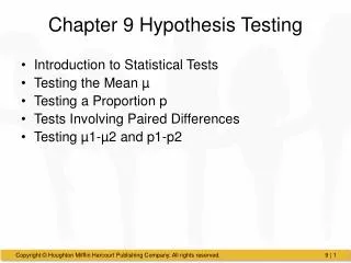
Impact Testing Impact Testing Charpy Impact Testing (a) Charpy impact testing machine. (b) Charpy impact test specimen. (c) Izod impact test specimen.
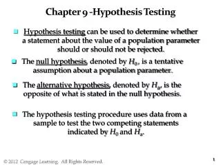
Energy Absorbed vs. Temperature Energy absorbed versus temperature for a steel in annealed and in quenched and tempered states. (Adapted with permission from J. C. Miguez Suarez and K. K. Chawla, Metalurgia-ABM, 34 (1978) 825.)
Temperature Effect on Fracture Surface Effect of temperature on the morphology of fracture surface of Charpy steel specimen. Test temperatures Ta < Tb < Tc < Td. (a) Fully brittle fracture. (b, c) Mixed-mode fractures. (d) Fully ductile (fibrous) fracture.
Charpy Testing of Steel: DBTT Results of Charpy tests for AISI 1018 steel (cold drawn).
Drop-Weight Test Specimen Drop-weight test specimen.
Charpy V-notch Curve Charpy V-notch curve for a pressure-vessel steel. Note that the NDT temperature determined by the drop-weight test corresponds to the high-tough region of the Charpy curve. Pneumatic pressurization; material: 21/4 Cr-1 Mo steel, yield stress 590 MPa. (After W. J. Langford, Can. Met. Quart., 19 (1980) 13.)
Oscilloscope Record (a) Typical oscilloscope record of an instrumented Charpy impact test. (b) Schematic representation of (a).
Fracture Toughness Test Specimens Typical ASTM standard plane-strain fracture toughness test specimens. (a) Compact tension. (b) Bending. (c) Photograph of specimens of various sizes. Charpy and tensile specimens are also shown, for comparison purposes. (Courtesy of MPA, Stuttgart.)
Load Displacement Curves vs. Fracture Toughness Test Schematic of typical load–displacement curves in a KIc test.
Plastic Zone at Crack Tip Plastic zone at the x1 crack tip in a plate of finite thickness.
Displacement Measurement Assembly for measuring displacement in a notched specimen.
Variation of Kc with Specimen Thicckness Variation in Kc with flaw size, specimen thickness, and specimen width.
Plastic Hinge Mechanism “Plastic hinge” mechanism of deformation.
J-Integral Testing Method for determining JIc. (a) Load identical specimens to different displacements. (b) Measure the average crack extension by heat tinting. (c) Calculate J for each specimen. (d) Plot J versus a to find JIc.
Flexure Test Normal stresses along a section of beam for linearly elastic material.
Three-Point and Four-Point Bend (Flexure) Tests TThree-Point Application of loads and bending moment diagrams for (a) three-point bending and (b) four-point bending tests.
Miniaturized Specimen:Four-Point Bending Shematic drawing of the miniaturized disk-bend test. (Adapted from H. Li, F. C. Chen, and A. J. Ardell, Met. Trans A, 22 (1991) 2061.)
Fracture Testing Methods for Ceramics Fracture-testing methods for brittle materials. (a) Double-cantilever beam (DCB). (b) Double torsion. (c) Notch flexure.
Chevron Notch Test Chevron notch test. (a) Schematic of the test arrangement and the details of the notch plane. (b) The chevron tip length, a0, can be measured from optical micrographs of broken specimens. (c) Chevron short-rod specimen.
Hardness Indentation in Brittle Materials Fractures produced by hardness indentations in (a) AsS3 glass (courtesy of B. R. Lawn and B. J. Hockey) and (b) Al203.
Plastic Deformation and Crack in Indentation of Brittle Material Schematic representation of indentation generating a plastic deformation region and a semicircular crack.
Fracture Toughness: Comparison by Different test Methods Comparison between conventional and indentation fracture toughness determinations for glasses and ceramics. (From G. R. Anstis, P. Chankitul, B. R. Lawn, and D. B. Marshall, J. Am. Cer. Soc., 64 (1981) 533.)
Adhesion of Thin Film to Substrate: Testing Indentation tests for the determination of toughness of bond between substrate and thin film; (a) method used for ductile coating on brittle substrate (typical of electronic components); (b) method used for brittle coatings on ductile substrate; (c) calculated normalized energy release rate as a function of normalized crack diameter. (Adapted from J. J. Vlassak, M. D. Drory, and W. D. Nix, J. Mater. Res., 12 (1997) 100.)