Download
1 / 21
240 likes | 570 Vues
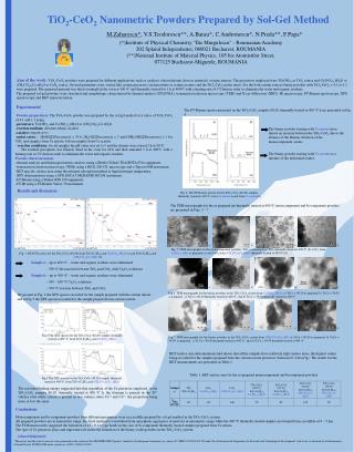
This study explores the synthesis of TiO2 nanoparticles using the sol-gel method, examining the influence of polyethylene glycol on particle morphology and crystallization. TiO2 exhibits a particle size ranging from 10 to 50 nm, with structural transitions from anatase to rutile at elevated temperatures. Additionally, we analyze the synthesis of Au-SiO2 composites, revealing the effects of heat treatment on particle size and coordination states in gold complexes. Findings highlight the potential applications of these nanoparticles in various fields, including catalysis and electronics.

E N D
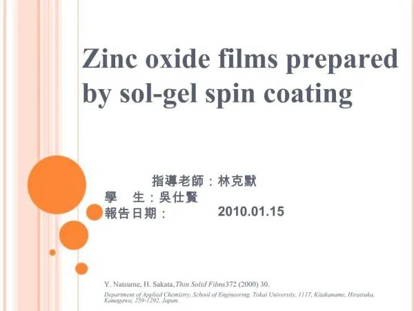
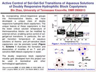
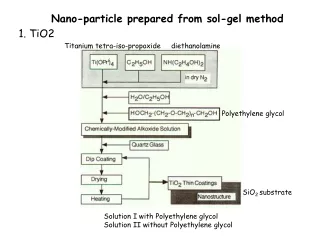
Nano-particle prepared from sol-gel method 1. TiO2 Titanium tetra-iso-propoxide diethanolamine Polyethylene glycol SiO2 substrate Solution I with Polyethylene glycol Solution II without Polyethylene glycol
Solution I Particle size 10~15nm. Space with a width of several nanometers existed between the crystallites. Anatase phase transforms to rutile above 650oC Solution II Dense structure, Particle size ~15nm and connected each other. Particle size increases to ~50nm heated above 650oC and the crystallites had connected hard each other.
Anatase powder The relatively high intensities indicates that a significant amount of the crystallites arranged with c axis perpendicular to the surface amorphous
2. Au-SiO2 TEOS+C2H5OH HAuCl4·4H2O+H2O +C2H5OH+HCl TEOS : H2O :C2H5OH: Au =1:2~10:0.4:2:0.028 r= H2O/TEOS mixing and stirring vigorously at room temp for 5mins, then kept tightly in container at 40oC for various of time prior to dip-coating Dip-coated film is transparent and almost colorless, film is heated at 500oC for 10mins, the film exhibits red to purple color
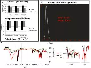
MAE: monoethanolamine NHC2H4OH 227nm and 314nm are assigned to 1Ag1g→1E1u and 1Ag1g→1E2u. The changes of the intensities of the peaks suggest the change in the coordination state in the gold complex
Effects of the exposure of the gel film to MEA vapor prior to heat-treatment • Decrease the size of gold particle to 5nm. • 2. Increase the amount of trapped gold particles in silica matrix. • Possible reasons • The pore size of silica matrix is smaller. • 2. Precipitation of gold hydroxide, smaller gold hydroxide particles are fixed in the gel. • 3. Change the coordination state of Au+3.
3. CdS in SiO2 gel TEOS, C2H5OH, H2O,HCl in molar 1:1:1:0.27 hydrated cadmium acetate C4H6CdO4·2H2O CH3OH 0.05: 1 C2H5OH, NH4OH in molar 4: 1.25 : 0.005 Dried in oven Dried gel Gel Heat treatment Heat treated in H2S at 200oC for 2hrs Journal ofCrystal Growth 144 (1994) 141—149
Dimethyl sulfoxide (CH3)2SO Heat treated to various temp Journal of solid state chemistry 118, 1-5 (1995)
Photonics and Nanostructures – Fundamentals and Applications 5 (2007) 156–163
CdS01 TEOS:Cd=1:0.5 Particle size 1.66nm CdS02 TEOS:Cd=1:1 Particle size 2.99nm Absorption peak for CdS bulk at 520nm
TiO2 tubules and fibrils (Ti(OCH(CH3)2)4(5ml) +C2H5OH(25ml) stirred at 0oC Add C2H5OH(25ml)+ H2O(0.5ml) +0.1MHCl(0.5ml) at 15oC After 60 s at 15oC the resulting mixture turned milky white (sol formation). alumina template membrane was immediately dipped into this solution for an immersion time that was varied between 5 and 60 s. dried in air for 30 min at room temperature. placed in a tube furnace (in air), and the temperature was ramped (50 °C h-1) to 400 °C. The membranes were heated at this temperature for 6 h, and the temperature was ramped back down (30 °C h-1) to room temperature.
氧化鋁濾膜 AnodiscTM13(0.2m, 膜厚50 m) 反面 剖面 正面
Electron Microscopy. SEM images of the 200 nm diameter tubules and fibrils were obtained as follows: One surface layer was removed, and the membrane was glued to a piece of paper towel. The membrane was glued with the polished face up. The resulting composite was immersed into 6 M aqueous NaOH for 10 min in order to dissolve the alumina. When the sol was 5 °C, thin-walled tubules were obtained even at long immersion times (1 min). In contrast, when the sol was maintained at 20 °C, solid TiO2 fibrils were obtained even after very brief (5 s) immersion times.
Bundles of the TiO2 nanostructures were observed. The bundle sizes observed ranged from as small as 2-4 fibrils to as large as 10 or more fibrils. The main feature in figure that runs diagonally across the image consists of two bundles of fibrils, one on the right edge of the main feature and one on the left edge. In this case the bundles consist of approximately 3-4 fibrils. A second set of two bundles is observed below this main feature; this second set of bundles also proceeds diagonally across the image but at a smaller angle. TEM image for TiO2 Fibrils Prepared in the membrane with 22 nm diameter pores.It shows a bundle of 15 nm diameter TiO2 fibrils.
To 20 mL of ethanol was added 0.35 g of zinc acetate, and the resulting mixture was boiled until a clear solution was obtained (ca. 30 min). The volume was returned to 20 mL with ethanol, and 0.06 g of LiOH·H2O was added. The resulting solution was ultrasonicated until a white suspension was obtained (ca. 1 h). The alumina membrane was immersed into this sol for 1 min, removed, and allowed to dry in air at room temperature for 30 min. The membrane was then heated in air at 120 °C for 6 h.
Nano-battery AgI-Ag nanowires (a) Cross-sectional FE-SEM image of AgI/Ag embedded inside the AAO membrane. ( b) FE-SEM top-view image.
The ionic conductivity of single AgI/Ag was estimated to be on the order of 1.5–8.0 × 10⁻³ (-cm)–1 Compared with that of room-temperature bulk polycrystalline AgI (ca. 10–5–10–6 (-cm)–1 an enhancement by two to three orders of magnitude was demonstrated. This enhanced ionic conductivity may be attributed to interfacial defects and mesoscopic multiphase effects as a result of stacking-fault arrangements.