Designer Soap Making
Designer Soap Making. A Team Project from Concept to Completion. 2. 3.

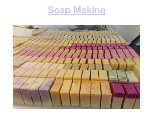
Designer Soap Making
E N D
Presentation Transcript
Designer Soap Making A Team Project from Concept to Completion
A hyperlink page has been included to allow you to view parts of the slide show on an as-needed basis.This tutorial may be run simultaneously with the solid modeling software and the Cam package, allowing the user to move between them. 4
Select the Item You Wish to View Introduction Creating All Tool Paths ----------------------------------- Assigning Tool Bits Activity Overview Teamwork Guidelines Verifying a Roughing Cycle Printing Slide Notes Verifying All Tool Paths Mold Cavity Design Creating the CNC Code Mass Properties Milling the Mold Cavity Exporting From Inventor Suggestions for Pouring the Mold Exporting From Mechanical Desktop Supplies on the Internet The End
Before viewing this presentation, you should print the slides in handout format to enable you to take detailed notes. Exit the slide show and follow the directions below. Pick File Pick Black & White Pick Print By activating print in this manner, you are able to configure the type of output as in the dialog box to the right. Pick Handouts (2 or 3 slides per page) then pick OK 6
This activity uses: • The Team Design Approach • Solid Modeling software: AutoDesk Inventor or Mechanical Desktop 3.0 • Cam Software: Surf Cam • CNC mill control software for Prolite Machines • Prolite 1000 Machining Center • Machineable wax • Clear glycerin soap, food coloring, fragrance oil, non-stick cooking spray • Microwave oven, plumber’s putty, clamps, candy thermometer 7
First, we design the mold, using AutoDesk Inventor or Mechanical Desktop 3.0 The following slides are from a part replay sequence. 9
1” Extrusion 11
Profile of mold cavity Planar parallel work plane with offset of 1/2” Draft angle is 8 degrees. [90 - 82 = 8] 12
Boat clip art has been added and extruded Sprue profile Mold halves are combined, later a part split will create each half 14
Sprue profile has been extruded with a draft angle of 20 degrees 15
Part split completed All corners filleted 17
The volume of glycerin soap required can be determined by comparing the mass property of Volume for the solid block with that of the mold cavity block. 19
Pick File, then Save Copy As Set the Save As file type to SAT and pick Save 20
Use the AMACISOUT command to translate the model’s geometry into a format that can be read by SurfCam 21
This is the correct folder in which to place the Amacisout file Make sure the file extension is sat 22
Now we will convert the solid model of the mold into tool paths using a CAM package called Surf Cam. 23
Launch SurfCam and import the SAT file using the sequence illustrated in the following slides Pick 1 Pick 2 24
Set up these dialog boxes as indicated by the arrows 25
When the Sat file has been successfully translated, pick Close Sat file as it should appear in SurfCam. Note: the yellow arrows are obstructing the view of some details. In the next slide, we will turn them off. 26
The next 2 slides will illustrate how to eliminate the yellow arrows that sometimes block the user’s view of wireframe elements Pick 1 Pick 2 Pick 3 27
The wire frame will be free of yellow arrows after shaft size is set to zero, then pick OK 28
Now the viewing direction will be changed to Isometric To produce the Isometric view Then double click here Pick View first 29
It is very important to make sure the top surface on the lower left corner of the model is at the coordinates of 0, 0, 0 The following 4 slides will illustrate how to move the top surface of the lower left corner of the model to that location 30
Move cursor to this point and left click 31
Leave all values at zero and pickOK Pick 32
Zoom Extents to center image The move function should produce the XYZ label on the top of the part in the lower left corner 33
From the Main menu pick Files Saveyour work after each major step using the following procedure The first time the file is saved, use the Save As command. This allows you to check for the proper destination folder. This is the correct folder, in the filename box enter a name and pick Save 34
We now must Mask out the wireframe components which do not need to be machined Pick the Mask icon Third, pick here then pick OK Pick 2 35
We will now select the color to apply to the non-machined wireframes Select dark green from the color palette. From the Main menu, pick Edit The next pick is Color 36
Use Intersect Pick here and drag across to lower right This will produce a yellow selection box. All surfaces under it will be turned green and masked from cutter tool paths. 37
Mask both hole surfaces using the Within selection mode. The holes will be worked on after the mold cavity toolpaths are finished Continue masking the outside vertical surfaces as well as the top surface The green surfaces are now masked from any machining activity 38
Now would be a good time to save. Always answer YES to both of the following dialog boxes while saving The mold cavity and sprue surface are now ready for cutter tool path application 39
Pick 4 First, pick NC from the Main menu Set Masking color to White Pick 3 Pick 2 40
Pick 3 Pick 2 Pick 4 First set mask to Yes 41
This is the tool bit selection dialog box. Here we will select the cutter bit, set the speed and feed rate, depth of cut and width of cut. For this mold cavity, we will use a 1/2” ball mill for the roughing cycle, a 1/4” ball mill for two intermediate planar cycles, (on both the X and Y axes) and a 1/8” ball mill for the Registration pin Holes and the final cleanup of the mold cavity. Pick here to select the tool bit 42
Pick this tool then OK 43
The actual tool number will depend on how you have set up the tool library in the machining center software. Adjust the parameters indicated by the arrows then select the Cut Control tab The spindle speed and feed rates used in this tutorial are for machinable wax only. 44
Adjust the parameters indicated by the arrows, then pick the Z Rough Pocket Options tab 45
Adjust the parameters indicated by the arrows, then pick OK 46
Pick 1 Second, pick on this white line Third, pick on this white line After the third pick, you will see a tool path simulation, then pick Accept 47
The Operations Manager dialog box keeps track of the various tool paths created, allows the graphical verification of tool paths, and gives the user the ability to change the order of machining operations by dragging and dropping Pick the Operations Manager Press F8 to hide the tool path in the Surf Cam screen. This will keep the screen from being too cluttered as more tool paths are added. Pick Done to return to Surf Cam Tool path description, eventually several more will be listed 48
We will now activate a graphical verification of the previously applied tool path - Pick the Operations Manager Next, pick Surf Cam Verify First, pick NC Project 49
Pick here to add stock to the model X, Y, Z values must all be zero for Corner 1 For Corner2,the X + Y values must match the stock, with the Z axis set to a negative thickness value Pick Add after all values have been entered 50