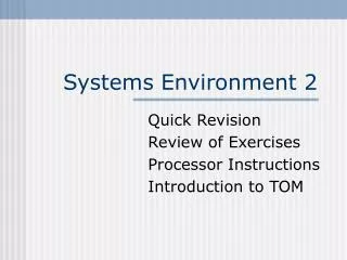
Systems Environment 3
Systems Environment 3. Quick Revision Review of Exercises Introduction to TOM TOM Exercises. Quick Revision. Processor Instructions. Diagram 3 The CPU Level. RAM. Control Unit. Registers. Near the control unit is the Program Counter (PC)

Systems Environment 3
E N D
Presentation Transcript
Systems Environment 3 Quick Revision Review of Exercises Introduction to TOM TOM Exercises
Diagram 3The CPU Level RAM Control Unit Registers Near the control unit is the Program Counter (PC) This indicates which instruction is currently being processed. The most Important of the registers is the Accumulator (ACC) ALL Data and Instructions must pass through the here. Arithmetic & Logic Unit
Processor instructions are normally split into two parts: The Operation Code which is written to the IR The Operand which is written to the MRB IR Instruction Register MRB Memory Read Buffer Processor Instruction Set Note that some instructions consist only of an Op Code, and do not require Operands. Op Code Operand IR MRB
Instruction Types Instructions beginning STx • These are instructions to STORE data at some RAM Memory Location Instructions beginning LDx • These are instructions to LOAD Data into the Accumulator Instructions beginning ADx • These are instructions to ADD data to the contents of the Accumulator
Instruction Types Instructions ending xxI • These instructions use the Immediately following operand as the data Instructions ending xxD • These instructions use the operand as an Address Directly to Access the data Instructions ending xxN • These instructions use the operand as an address iNdirectly, to locate the address where the data is to be found.
Instruction Types Instructions not requiring an Operand: IN • This inputs data into the processor from an external source OUT • This outputs data to the VDU STP • This stops the processor.
LDI 34 STD 25 ADN 43 Examples What precisely, do these instructions mean?
LDI 34 STD 25 ADN 43 Loads 34 Immediately into the Accumulator Stores the contents of the accumulator at memory address 25 Finds memory address 43, there goes to the location specified there. Takes the data at this second location and adds it to the value in the accumulator Examples
More Instructions These commands work by changing the value in the PC These instructions all divert processing to different locations in RAM: JMP xx • The program counter changes to XX and processing continues from there. JZ xx • If the Accumulator is Zero, the program counter changes to xx and processing continues from there. JMI xx • If the Accumulator is Negative, the program counter changes to xx and continues processing from there.
137 LDD 138 200 139 ADD 140 201 141 OUT 142 STD 143 200 144 LDD 145 202 146 SUB 147 203 148 STD 149 202 150 JZ 151 154 152 JMP 153 137 154 STP Activity 1(Booklet, Exercise 5) Translate this program into full instructions, Then execute the program, to see what effect it has.
137 LDD Load Directly 138 200 from location 200 139 ADD Add Directly 140 201 from location 201 141 OUT Output 142 STD Store Directly 143 200 in location 200 144 LDDLoad Directly 145 202 from location 202 146 SUB Subtract (Directly) 147 203 from location 203 148 STD Store Directly 149 202 in location 202 150 JZ If Accumulator Zero, Jump 151 154 to instruction 154 152 JMP Jump 153 137 to instruction 137 154 STP Exercise 5 Solution (part 1)
200 0 201 5 202 10 203 1 204 0 AC OUT Program Execution 137 LDD 138 200 139 ADD 140 201 141 OUT 142 STD 143 200 144 LDD 145 202 146 SUB 147 203 148 STD 149 202 150 JZ 151 154 152 JMP 153 137 154 STP
200 50 201 5 202 0 203 1 204 0 AC 0 OUT 50 Exercise 5 Solution part 2Final State of Registers 137 LDD 138 200 139 ADD 140 201 141 OUT 142 STD 143 200 144 LDD 145 202 146 SUB 147 203 148 STD 149 202 150 JZ 151 154 152 JMP 153 137 154 STP
Program (name) Begin do things End If (condition) Then do things Else do things Endif For Count = 1 to X do things EndFor While (condition) do things EndWhile Write (number) Read (number) A: = (something) PseudoCode Commands
Program CountUpInFives Begin Answer:= 0 Countdown:= 10 While Countdown <> 0 Answer: = Answer + 5 Write (Answer) Countdown: = Countdown – 1 EndWhile End Exercise 5 Solution Part 3 This summarises what the program does in a more succinct manner.
Program Pre_TOM Begin Read (Number) While Number <> 0 Write (Number) Read (Number) EndWhile End Exercise 5.2 PseudoCode What is the machine level code for these instructions?
Program Pre_TOM Begin Read (Number) While Number <> 0 Write (Number) Read (Number) EndWhile End Exercise 5.2Solution The program has been put into memory at location 200. This is completely arbitrary. 200 INP 201 JZ 202 206 203 OUT 204 JMP 205 200 206 STP
TOM Totally Obedient Moron
What is TOM? • First of all, TOM is a CPU simulator which allows you to run short CPU programs and a lot more. • You need to access H:/Tomfile and download all the files in the folder to your A: drive. • Double-Click on TOM.exe and you will get this dialogue box.
RAM Memory Locations, where the program will be stored: Click-Able Keys to input, edit and clear Instructions. Program Counter Output Device Accumulator Control Buttons
Getting to know TOM • Clicking ‘Help’ on the toolbar brings up this screen. After this session you should spend some reading the first 6 sections. • Here we are going to dive straight in to the instruction Set (4th on the list) • TOM’s Instructions are very like (but not exactly the same as) the ones we have seen.
Tom’s Easy Instructions The following is alist of the first 12 of TOM’s instructions: 0HALTHLT 1 LOAD ACCUMULATORLDA 2 STORE ACCUMULATORSTO 3ADD TO ACCUMULATORAC+ 4SUBTRACT FROM ACCUMULATORAC- 5 MULTIPLY ACCUMULATORACX 6DIVIDE ACCUMULATORAC\ 7 JUMP UNCONDITIONALLY JMP 8 JUMP IF ACCUMULATOR NEGATIVEJM- 9 JUMP IF ACCUMULATOR IS ZEROJM0 10 JUMP INDIRECTJ() 11 INPUT A NUMBER TO ACCUMULATORINP 12 OUTPUT A NUMBER FROM THE ACCUMULATOROUT
Our First TOM Program At the top of the TOM window, click on: File – Open then select: wexampl1.tom from the menu.
This is the disassembled version of the program. In order to see this, you should click on: Options – Disassemble NB: Assembled = “in Numerical form” Disassembled = “In mnemonic code form TOM Example 1
Run the Program. The yellow highlight will move down the screen. What else happens? Running Example 1 RUN
Running Example 1 So, what exactly did the program do? The program is now in Assembled form Program Counter shows 2 The value 55 has been printed out. Accumulator shows 55
Loaded the value 55 into the Accumulator, from location 24 Output the value in the Accumulator to the Printer Stopped Processing. What Example 1 Did:
Load in Example 2, and use the assembled (left) or the disassembled version (right). Say what effect each line will have. Trace through the program to work out what exactly will happen. Run the program to see if you were right. TOM Example 2
Input a number from the Keypad into the Accumulator Store the number at location 12 Add the number stored at location 12 to the value in the Accumulator Output the value in the Accumulator to the printer Stop processing TOM Example 2 The task performed by the program was to add the two input numbers, and print out the answer.
Try to create a program to do the following: Input two numbers from the Keypad into the Accumulator Store the numbers at locations 12 and 13 Subtract the second number entered from the first Output the answer Stop processing TOM Challenge Work on paper first. When you feel that the program you have created is correct, then type it in and run it.
00 Input a number 01 Store at location 12 02 Input a number 03 Store at location 13 04 Load acc from location 12 05 Subtract value from location 13 from accumulator 06 Output the value in the accumulator 07 Halt TOM Challenge - solution Disassembled version Assembled version
Activity 4 You should now open in turn, Examples 3 and 4 from the disk. In each case you should: • Make a written copy of the program in disassembled form. • Explain what effect each line of the program will have • Trace through the program to see its effect on the accumulator, memory locations and output. • Run the program to see whether you are correct • Briefly summarize what task the program is performing. You may find it helpful to read TOM’s Help File (the first 6 sections)
Exercise 6.1 You are asked to write a pseudo code design for these specifications: Exercise 6.1.1 Input: Numbers from Keyboard Output: Each Number entered Termination: Zero
Input: Numbers from Keyboard Output: Each Number entered Termination: Zero Program Pre_TOM Begin Read (Number) While Number <> 0 Write (Number) Read (Number) EndWhile End In fact, this is precisely the program we saw in Exercise 5.2 We now need to change this to a TOM Program
The program is just the solution from ex.5.2 in terms of TOM’s instructions. It is a simple translation from one “dialect” of machine code to the other. 6.1.1 TOM Solution
Activity • Now work in groups to complete exercise 6 • Intitially do parts 2-5 • If you feel confident, you can go on to 6,7 and 8, but you may need to read the helpfile for more TOM commands.