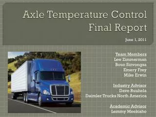
Axle Temperature Control Final Report
Axle Temperature Control Final Report. June 1, 2011. Team Members Lee Zimmerman Boun Sinvongsa Emery Frey Mike Erwin Industry Advisor Dave Ruuhela Daimler Trucks North America Academic Advisor Lemmy Meekisho. Background Information. 21 st Century Truck.

Axle Temperature Control Final Report
E N D
Presentation Transcript
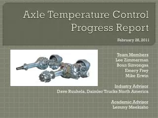
Axle Temperature Control Final Report June 1, 2011 Team Members Lee Zimmerman Boun Sinvongsa Emery Frey Mike Erwin Industry Advisor Dave Ruuhela Daimler Trucks North America Academic Advisor Lemmy Meekisho
Background Information 21st Century Truck 2.25% of energy required to operate a truck at a steady highway speed is lost in the drivetrain
Background Information Axle Temp. Project Specs, 2010 Increasing the axle fluid temp will reduce energy loss Up to a 0.7% improvement in drivetrain efficiency possible (apprx $600/year in savings in fuel costs)
Requirements • Top PDS requirements • Efficiency gain • Device must achieve a net gain in efficiency • Return on investment • 2 year payback period (apprx $1200 budget) • Temperature control • Achieve/maintain fluid temp of 65-80ºC (ambient above freezing) and 50-65ºC (ambient below freezing) • Warm-up rate • Achieve a warm-up rate of 2X current state (est. 2ºC/min)
Design Concepts Heat Exchanger – Uses exhaust gas or engine coolant as a heat source Electric Heater – Resistance heater that obtains power from truck’s charging system Active Insulation – Relies on internally generated heat and has some form of cooling
Concept Selection Active insulation concept selected -most reliable without compromising efficiency - simple to manufacture - utilized waste heat - inexpensive components - little to no modification to existing components - no additional energy requirement
Insulation Design A solid insulating shell made of expanding foam insulation was designed to retain internally generated heat while being able to stand up to harsh driving conditions. Initial testing indicated that insulation would more than achieve the necessary temperature range while nearly satisfying the desired warm-up rate.
Heat Sink A heat sink was designed that would replace an access cover on the front of the differential The large heat load in extreme operating conditions required the heat sink base be as large as possible, with the number of fins calculated from an adiabatic fin tip approximation
Heat Sink Sheild The heat sink needed to be shielded from airflow during the warm up phase, but also required maximum airflow when cooling was required The team designed a enclosure that would swing open to completely expose the heat sink to impinging air while creating a path for flow
Prototype Testing Uninsulated axle fluid warm-up rate to 30°C delta: .92 °C/min average Prototype axle fluid warm-up rate to 30°C delta: 1.4 °C/min average 52% improvement in warm up rate
Prototype Testing With heat sink exposed the axle fluid temperature stabilized, meeting the goal criteria, but it did not cool as expected.
Performance Analysis Explanations for heatsink performance were generated
Follow-up Testing Static Oil Level, Level Ground Oil Level with Constant Velocity To test hypothesis, a clear acrylic cover was attached to axle and viewed with camera
Conclusion Complex dynamics and shape of axle made design difficult to model Many assumptions had to be made Important parameters had to be estimated (convection coefficient) Testing of assumptions was important to prove functionality