Response property between fiber and MPPC on ECAL Prototype
280 likes | 500 Vues
Response property between fiber and MPPC on ECAL Prototype. 2011 年 03 月 03 日 High Energy Physic Laboratory Choi Weon Seok. Purpose : Problem of ECAL Prototype. MPPC. Effective pixels contacted with WLS. Scintillator. MPPC. 1mm. 1mm. WLS-fiber.

Response property between fiber and MPPC on ECAL Prototype
E N D
Presentation Transcript
Response property between fiber and MPPC on ECAL Prototype 2011年 03月 03日 High Energy Physic Laboratory Choi Weon Seok
Purpose:Problem of ECAL Prototype MPPC Effective pixels contacted with WLS Scintillator MPPC 1mm 1mm WLS-fiber Surface of MPPC • Location of hole is not fixed • This effect might cause change of effective pixel number for every MPPC on ECAL prototype. Hole for WLS-fiber
Purpose: Response Curve of MPPC • Maximum photon number which MPPC can detect in an event, is limited by pixel number of MPPC itself. ⇒MPPC response looses linearity to incident photon number • Response Curve would be affected by MPPC/fiber mismatch Detected Photon number of MPPC It is needed to search saturation curve for every MPPC on ECAL prototype. Real Photon number(PMT response)
Scintillator Polarlizing plate x2 glass lense WLS- fiber Pico-secLASER λ: 408nm PMT MPPC Experiment: Setting PMT • Pico-second LASER is used as light source. • Intensity is adjusted by two polarizing plate. • PMT is applied to estimate real photon number. • Light source for PMT is the LASER reflected by glass .
Experiment:Response Curve (effect of MPPC/fiber mismatch) Photon number of MPPC detected scintillator MPPC • The effective number of pixels decreases as MPPC/fiber mismatch increases before Before WLS-fiber after After Lifting up PMT response
FittingFunction Real photon number(PMT response) y : Photon detected by MPPC Effective pixel number of MPPC Photon Detection efficiency N pix Experiment:Response Curve (effect of MPPC/fiber mismatch) • Fitting function above doesn’t fit well the data in the whole x range. ⇒ use the function above in low x range, and evaluate
Experiment: Correlation of Npix &MIP const • Possible reasons for data dispersion are, • accuracy of estimated by fitting • change of the state of MPPC/fiber mismatch Yaxis: MIP calibration constant (at 2008/2009 Fermi Lab)
Conclusions&Tasks Conclusions • I’ve measured MPPC response curve with pico-second LASER. ⇒It seems like time structure of incident light affects a lot. • The effect of MPPC/fiber mismatch on response curve has been measured. ⇒ It is needed to find response curve for each MPPC on ECAL prototype. • By evaluating with fitting function and comparing it with MIP const, it seems like there is correlation between them. Tasks • Research to understand response curve more deeply. • Confirming the state of MPPC/fiber mismatch by measuring cosmic muon and compare with FNAL data.
:linear equation The Way of Estimation • When you differentiate ideal fitting function、you will getThus, I determined the fitting range by searching linear data range when plotting difference quotient data. 元のslideに戻る(Click)
:xに対する1次関数 The Way of Estimation • 理想の fitting 関数を微分してみると、もし、測定結果の分布の差分を取って直線的な傾向があるように見えるところがあれば、そこでは時間構造の影響が少ないと思われる。 ⇒この範囲でfitting. 元のslideに戻る(Click)
The Way of Estimation 元のslideに戻る(Click)
Reforming Fitting Function • It is obvious that the gradient changes gradually. (slide 11) • There are two parameters which can affect gradient, εand Npix.(slide10) • Assuming εdepends on x like , and replace this function with 元のslideに戻る(Click)
Correlation of new Npix/MIP const (72 MPPCs) r: 0.55 元のslideに戻る(Click)
Experiment: Setting Scintillator PMT LASER 元のslideに戻る(Click)
Purpose: Response Curve linear • Geiger modeで動作させるMPPCの各pixelは、同時に光子が入射しても一定の信号を出す。 ⇒入射光子数が多くなくと、応答の線形性が落ちる 入射光子数 MPPCの検出光子数 MPPCの有効 pixel数 真の光子数 :光子検出効率 実際にはPMTの応答を用いる MPPCの検出光子数 元のslideに戻る(Click)
Experiment:Response Curve 元のslideに戻る(Click)
Simulation results: when incidence light has time structure • 入射光が時間的構造を持っているとき、理想的なsaturationは起こらない. • このときは理想的なsaturation の式ではfittingできない. By Mr. Sudou (Tsukuba Univ.-2008) 元のslideに戻る
Scintillatorを通したときの応答曲線 1600pixel 400pixel By Hiroko Koike (tsukuba-2010) • 高い領域でよりは Fittingできているように見えるが、(x軸)低領域では時間構造 の影響が少ないからだと思われる. 元のslideに戻る
MPPCに直接入れて見たとき • MPPCに直接LASERを入れたときの分布。 Scintillatorのときに比べては小さいが、徐々に上がる成分は少し見える。 ⇒LASERそのものの時間構造によるものと思われる。 元のslideに戻る
Response Curve with non fiber scintillator(kuraray) 元のslideに戻る(Click)
PMTの印加電圧設定 PMTの増倍率 • 真の光子数に対応させるPMTの応答が入射光子数に対して線形性を失うと扱えない. • LASERの強度を最大にしたときの印加電圧によるPMTの増倍率の様子を調べて印加電圧を設定 元のslideに戻る(Click)
反射光&WLSを用いるときのPMTの応答 • これまでは、応答曲線を調べるときには、scintillatorの光をfiberで集め、両端をそれぞれMPPC,PMTに入れて測定 • しかし本実験ではそれができないため、反射波を用いる。 ⇒反射波とfiberに対してのPMTの反応が線形性を持つかを見る必要がある 元のslideに戻る(Click)
LASER • The LASER used is Picosecond Injection LASER(PiLAS) of Advan-ced Laser Diode Systems • It is possible to adjust intensity by changing “Tune” parameter. Every data are measured under Tune 50%. 元のslideに戻る(Click)
d MPPCの検出光子数の計算 Low gain mode(ampなし) High gain mode D 1 光子に対する積分電荷量(d)を測定 光源に対する応答の積分電荷量( D )を測定 ampの増倍率を補正して、ampなしの時の1光子に対する積分電荷量( )を計算
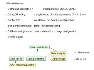
Contents • Backgrounds • Purpose • Problems • Response Curve of MPPC • Experiment • Setting • Response Curve • Conclusion&Tasks