Download
1 / 36
380 likes | 506 Vues
This paper explores the design of a fast-locking PLL with low-jitter performance for mobile applications. It introduces an advanced all-digital PLL architecture that aims to provide stability, programmability, and portability. The proposed architecture features a fine-search delay matrix to enhance resolution and reduce output jitter. The paper discusses the major building blocks, operation, and optimization techniques for the ADPLL controller and digital loop filter.

E N D
All Digital and Integrated PLL Presented By: Adel Tarek Ahmed Mohamed El-Mahdi Amir AmirZarkani Mohamed Salem Madonna Said
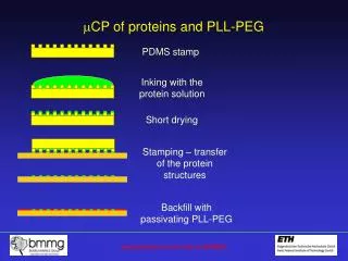
PLLRecap: • PLL can be found in various system applications where data needs to be clocked. • PLLs are used in frequency synthesis applications like FPGA and Microprocessors • PLL is a feedback system that generates a signal that has a fixed relation to the phase of an incoming reference.
Introduction What characteristics are need for mobile or portable applications? • Fast entry and exit from power management techniques. • Jitter less than 4% of the clock cycle time is typically needed to avoid functional failures in a microprocessor . • Thus the aim of this paper is to design a fast-locking PLL with low-jitter performance in a short period. • Due to high integration of very-large-scale integration(VLSI) systems, PLLs often operate in a very noisy environment.
There has been many analog approaches to compensate for this such as: • Narrow bandwidth or using a low-gain voltage-controlled oscillator. • Which bring us to our main topic all-digital phase-locked loops (ADPLLs). • Which has proven to present us with better stability, programmability, testability and portability. • But like engineering taught us best, nothing is perfect. ADPLLs have low sensitivity, resolution limitations and its jitter performance is way worse then that of the analog. • The ADPLL proposed can achieve fine resolution and fast lock-in time, however, its digitally controlled oscillator (DCO) needs to be fully custom designed, making it difficult for porting to different processes as design requests. • A fine-search delay matrix architecture is developed to improve the DCO’s resolution.
Continued • Two DCOs will be used in order to reduce the output jitter effectively. • However the fine-search matrix requires a large silicon area and has a high power consumption. • Digital VLSI is proposed in this brief for a truly portable and cost-effective ADPLL-based frequency synthesizer solution.
ADPLL Architecture • There are four major building blocks in the proposed ADPLL, namely the phase/frequency detector (PFD), the DCO, the ADPLL controller, and the digital loop filter • The DCOs one is used for tracking the reference clock and the other is used for generating the output clock. • The output clock of INNER DCO is divided by then connected to the PFD. The PFD detects the frequency difference and phase error between reference clock (REF_CLK) and divided output clock (dco_out_divM). • It then generates an up (P_UP) signal or down (P_DOWN) signal to indicate that the INNER DCO should be speeded up or slowed down respectively.
ADPLL Architecture • Then the ADPLL controller updates the INNER DCOs control code: coarse [5:0] and fine [5:0] to adjust the output frequency of INNER DCO. This INNER DCOs control code is also sent to the loop filter. • In ADPLL controller, an adaptive search step is used when it searches for the target frequency. • The ADPLL’s closed-loop response time is determined by the response time of the DCO, the delay time of the ADPLL controller, and the frequency divider. • The worst case lock-in time for this frequency acquisition algorithm, in terms of reference clock cycles, is: • To further improve the jitter performance of the APDLL, the loop filter is used to filter out the resultant noise into the OUTPUT DCO. • the loop filter detects the maximum INNER DCO control code and minimum INNER DCO control code within (k) reference clock cycles and then outputs: (DCO control code (Max)+ DCO control code (Min))/2 as the average DCO control code for the OUTPUT DCO.
Circuit Design • The DCO is separated into 2 stages: A coarse-tuning stage and a fine-tuning stage.
Coarse tuning • In the coarse-tuning stage, the coarse-tuning delay chain with 64-to-1 select-path architecture is used to provide different delays for coarse tuning. • This architecture has the advantage of minimum intrinsic delay time in the path selector to improve operating frequency of the DCO. • It can be easily modified to meet different specifications for different applications. • To avoid a large loading capacitance appearing in the path selector’s output, the path selector is partitioned into two stages. • The delay time difference between two neighbor paths is determined by one coarse-tuning delay cell.
To increase the frequency resolution of the DCO, a fine-tuning delay cell is added after the coarse-tuning stage.
Fine tuning • The fine-tuning delay cell consists of an AND-OR-INV (AOI) cell and an OR-AND-INV (OAI) cell. • Both the AOI cell and the OAI cell are shunted with two tristate buffers. Shunted tristate buffers can increase the controllable range of the fine-tuning delay cell.
Phase/Frequency Detector: • When the divided output clock (FB_CLK) leads the reference clock (IN_CLK), flagD generates a low pulse and flagU remains high. • when FB_CLK lags IN_CLK, flagU generates a low pulse and flagD remains high. • PulseAmp. Increases the pulse width of OUTU and OUTD.
Digital Pulse amplifier It uses the cascaded two-input AND architecture to increase the pulsewidthof OUTU and OUTD. The digital pulse amplifier enlarges the phase error between IN_CLK and FB_CLK, thus, the following D-flip-flops can detect it. When the phase error is less than 50 ps, both flagU and flagD will remain in high, and no trigger signal is sent to the ADPLL controller.
ADPLL Controller/Frequency Divider/Loop filter Filter comparison frequency: One of the major functions of the loop filter is to remove unwanted components of the phase detection or phase comparison frequencies. If they appear at the input to the VCO, then sidebands will appear offset from the carrier by a frequency equal to the phase comparison frequency. Loop stability: The break points and roll off of the loop filter are of particular importance. The filter should be designed to give the required fall in loop gain at the unity gain point for the loop, otherwise the loop can become unstable. Transient response / tracking: In some applications it may be necessary for the phase locked loop to track another signal or change frequency. The loop filter acts to slow the response down. The narrower the loop bandwidth, i.e. the lower the cut-off frequency of the filter, the slower the response of the loop to responding to changes. Conversely if the loop requires a fast response to changes in frequency, then it will need a wide loop bandwidth.
A 283-GHz Fully Integrated Phase-Locked LoopBased on 65-nm CMOS
Introduction • Due to high data-rate communication and high precision systems, a stable signal source with a low phase noise is critically desired for frequency band near 300Ghz or higher. • Phase-locked loop (PLL) is highly favored as a free running oscillator because of, • its precise frequency control capability • signal integrity. There have been systems developed using high frequency ranges working at 245 GHz and 500 GHz using, PLL operating at lower frequency range + frequency multipliers. AdvantagesDisadvantages • Enhanced output power nonlinearity of additional circuits generate • Wider frequency tuning range undesired harmonics at output
Introduction Si CMOS PLL operating at around 283 GHz is developed using , • total division ratio of 16,384 based on injection-locked frequency dividers (ILFDs) • current-mode logic (CML) dividers • it works with a reference signal around 5.7 MHz
OscillatorDesign • N-push oscillators are widely used for oscillators operating at high frequency • N-push Colpitts Based Oscillator • The signals from each unit oscillator is combined at the common node • Phase difference of 2∏/N will be established between adjacent unit oscillators • Sufficiently large load impedance is needed • Phase diff. will lead to the cancellation of all the frequency • components including the fundamental signal, except for the Nth • harmonic signal at the common node where the output will be • extracted
Oscillator Design 2) N-push Ring Based Oscillator • Phase difference of 2 ∏ /N between adjacent stages will be guaranteed also • without load impedance. • Nth harmonic signal only also will be survived at the • common node .
Oscillator Design • Triple-push ring Oscillator will be used in this proposed architecture. • 1st Oscillator (OSC1) : Fixed frequency oscillator • 2nd Oscillator (OSC2) : Voltage Controlled oscillator (VCO) with integrated varactors • 3rd Oscillator (OSC3) : The actual final oscillator employed in the PLL.
Oscillator Design: The basic fixed-frequency oscillator (OSC1) • Three transistors (M1-3) • Three load inductors Ld,1-3, three series inductors Lg,1-3 : to determine the phase shift of each stage • RF choke L3f0, behaves as a frequency selective load which is adjusted to an electrical length of ʎ/4 at 3f0 to boost the output signal near 3f0 • VDDof 1.5 V, the drain current of each device was set to 14 mA, • Fmax ͢͢ : the unit gate finger width with a fixed given gate width 20 µm
Oscillator Design: The basic fixed-frequency oscillator (OSC1) • Gmwas calculated for 4 unit gate finger widths (the number of fingers) assuming a phase shift of 120° per each stage. • the optimal unit finger width is found to be around 1.43 µm, corresponding to 14 fingers the maximum available power gain (MAG) of a stand-alone transistor
Oscillator Design: The basic fixed-frequency oscillator (OSC1) • The identical oscillation frequency points and the identical output power points obtained on the Ld -Lg space. • For example, for an oscillation frequency of 300 GHz, a choice of (Lg, Ld) around (70 pH, 50 pH) would provide the maximum output power according to the result.
Phase Locked Loop Integration The PLL is composed of: • Triple push dual output VCO • Frequency Divider Chain • Charge Pump/Loop Filter The Frequency Divider chain is composed of two ILFDs and 12 CML frequency dividers
Injection-Locked Frequency divider ILFDs are known for high frequency operation with low dc power consumption and thus adopted for the first two divider stages in the chain. One concern for employing ILFDs is their rather narrow locking range, which may result in a failure of PLL locking if a precise frequency alignment is not achieved.
EXPERIMENTAL RESULTS • The integrated PLL was fabricated in Samsung 65-nm • CMOS technology, which exhibits fT/fmaxof 200/220 GHz. • The chip sizeexcluding the dc and RF pads is 920*520 micro meter square
The ILFDs are characterized for the locking range with the sensitivity curves • Zero dBm level as the reference. The measured locking ranges are up to 4 GHz and 6 GHz with a fixed tuning voltage for the 94- and 47-GHz ILFD, respectively. (Fig 1) While the output power of the 94-GHz ILFD is around 0 dBm, the VCO output power streaming into the 94-GHz ILFD is around -7 dBm. Hence, the practical locking range for the 94-GHz ILFD is estimated to be around 3 GHz from the sensitivity curve.
Both ILFDs consume dc power of 10.8 mW. To enable the operation verification of the entire divider chain, a test port was inserted at the output of the divider chain (Fig 2)At this test port, an output signal with a frequency that exactly matches f0/16,384 for the entire VCO tuning range emerged, indicating that an accurateoperation of the divider chain has been accomplished.
For the characterization of the integrated PLL, the same measurement setup as was used for the VCO was employed, except for the application of the reference signal that was injected by a signal generator (Agilent E8247C). (Fig 3)With the reference frequency swept from 5.743 MHz to 5.771 MHz, the output frequency of the PLL changed accordingly from 282.3 to 283.7 GHz, as indicated by the measured output signal (3f0) spectrum of the PLL shown in Fig. 15, which is a clear indication of a successful locking.
(Fig 4) compares the outputspectrum of the PLL in the locked state (a) and unlocked state(b),indicating the difference between the two states. It is notedthat the reference spur was not observed, presumably due to theheavy conversion loss of the external sub harmonic mixer in thishigh frequency band.
(Fig 5) shows the waveforms of thereference signal and the divided signal of the PLL in the lockedstate measured by a real-time oscilloscope. It showswell-synchronized time-domain responses of the two signals,another indication for the locking of the PLL.
(Fig 6) shows the measured phase noise of the PLL, which is -53.5 dBc/Hz at 100kHz (in-band) and -78.6 dBc/Hz at 10 MHz (out-of-band). It isnoted that the measurement was made with a commercial signalgenerator. If a crystal oscillator is employed, which typicallyexhibits a phase noise lower than commercial signal generatorsby a few tens of dB, the measured in-band phase noise wouldshow an improvement by a similar amount. Total dc powerconsumption of the PLL is 114 mW. Table III compares thedeveloped PLL with the reported Si-based PLLs operatingabove 100 GHz. As a fully integrated PLL based on CMOStechnology, the developed PLL in this work shows the highestoperation frequency.
CONCLUSION • An integrated PLL operating at 283 GHz based on a 65-nm CMOS technology has been developed, which does not include a frequency multiplier chain at the output. • Employing a triple-push ring VCO and a pair of ILFDs as high-frequency components. • The PLL exhibits a maximum output power of -22.5 dBm and a phase noise of -53.5 dBc/Hz at 100 kHz (in-band) and -78.6 dBc/Hz at 10 MHz (out-of-band) with a dc power dissipation of 114 mW. It is expected that the developed • PLL will provide a stable signal source for various applications that require precise frequency control at high frequency bands beyond 200 GHz