ALL-DIGITAL PLL (ADPLL)
ALL-DIGITAL PLL (ADPLL). Alicia Klinefelter ECE 7332 Spring 2011. Outline. Project Description Problem Expected Outcomes My Approach Basic Topology of All Digital PLLs (ADPLL) Components My architecture Initial Designs and Research Final Design Novelty Low power and synthesizeable

ALL-DIGITAL PLL (ADPLL)
E N D
Presentation Transcript
ALL-DIGITAL PLL (ADPLL) Alicia Klinefelter ECE 7332 Spring 2011
Outline • Project Description • Problem • Expected Outcomes • My Approach • Basic Topology of All Digital PLLs (ADPLL) • Components • My architecture • Initial Designs and Research • Final Design • Novelty • Low power and synthesizeable • Results • Further Work and Conclusions
PROJECT: ADPLL • Originally only planned to complete DCO. • In order to reduce number of lock cycles, pre-DCO logic needed. • Application space: Sub-threshold ADPLL Clock synthesizer for wireless sensor networks that takes a 50kHz reference and outputs a clock at 500kHz. • Phase noise and jitter constraints are not rigid • Assuming clock is controlling digital logic • Amount of jitter in this application will seem large compared to RF • Main goal is low power and using sleep mode after lock
PROJECT: ADPLL expectations • Power consumption: < 10uW • Supply Voltage: 400mV (Vt = 410mV for NMOS_VTG) • Phase Noise: < 60dBc/Hz @ 1MHz • Lock cycles: < 10 • LSB Resolution: < 1ns • Only gates used (no capacitors, inductors, etc.) • Some ADPLLs assume only intermediate signals are digital. • To attempt to make it synthesizeable
Why are ADPLLs useful? • Problems with analog implementation • Design and verification • Settling time • 20 – 30 msin CPPLLs • 10 ms in the ADPLL • Implementation cost • Custom blocks • Loop Filter • High Leakage current • Large capacitor (2) area • Charge Pump • Low output resistance • Mismatch between charging current and discharging current • Phase offset and reference spurs
Outline • Project Description • Problem • Expected Outcomes • My Approach • Basic Topology of All Digital PLLs (ADPLL) • Components • My architecture • Initial Designs and Research • Final Design • Novelty • Low power and synthesizeable • Results • Further Work and Conclusions
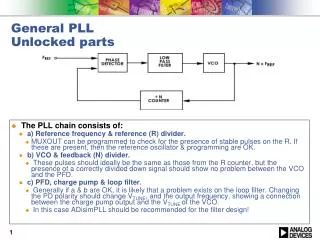
All-digital PLL (ADPLL) TOPOLOGY Why the loop filter? DCO ref(t) Digital Loop Filter Time-to-Digital Converter (TDC) out(t) Divider
Outline • Project Description • Problem • Expected Outcomes • My Approach • Basic Topology of All Digital PLLs (ADPLL) • Components • My architecture • Initial Designs and Research • Final Design • Novelty • Low power and synthesizeable • Results • Further Work and Conclusions
ADPLL: Time-to-digital converter I • Delay chain structure sets resolution • Mismatch causes linearity issues • Resolution: want low quantization noise DCO ref(t) Digital Logic Controller Time-to-Digital Converter (TDC) out(t) div(t) Divider • Architectures [1, Perrott]
ADPLL: Time-to-digital converter II • Perrottpresented a ring-oscillator based TDC • Counts number of pulses between the two rising edges of the clock • Determines which is leading /lagging • Output goes to digital logic block to control DCO • Large range with compact area • Difficult to find in literature used for ADPLL • Why would a filter be needed? [1, Perrott]
ADPLL: Time-to-digital converter II reset logic oscillator Final schematic of the TDC. 1.43μW @ 0.4V leading/lagging logic 9-bit up-counter registers<8:0>
ADPLL: DCO • Replaces the VCO from analog implementations • Consumes 50-70% of overall ADPLL power • Generally consists of a digital controller implementing frequency acquisition algorithm and oscillator. DCO ref(t) Digital Loop Filter Time-to-Digital Converter (TDC) out(t) Divider
DCO: DELAY CELLS • Many options • Standard inverter • Hysteresis Delay • Current Starved • Shunt Capacitor • Most low power applications for ADPLLs use inverters or hysteresis delay cells (for fine stage). • LSB resolution doesn’t need to be incredibly small for our application.
DCO: DELAY CELLS The four different delay cells that were investigated. Inverter Shunt Capacitor Hysteresis Delay Current Starved
output DCO: SCHEMATIC feedback Linear Range: 430kHz-680kHz Power (all on): 935.2nW Coarse tuning Fine tuning
DCO: FINE STAGE RANGE LSB Resolution: 692ps
DCO: Example output Coarse Code: 0010_0000_0000 Fine Code: 0000_0000_0000 0000_0000_0000 1000_0000_0000 0000_0000 Output Frequency: 650.2kHz
Outline • Project Description • Problem • Expected Outcomes • My Approach • Basic Topology of All Digital PLLs (ADPLL) • Components • My architecture • Initial Designs and Research • Final Design • Novelty • Low power and synthesizeable • Results • Further Work and Conclusions
ADPLL: LOGIC BLOCK • Takes number of pulses counted from TDC, determines the number of coarse and fine delay stages needed. • Uses one-hot encoding for the outputs of the transmission gates. • Once coarse/fine stages are known, uses headers to turn off delay cells not being used • Improvement on binary search • Uses initial number of pulses to determine where to start search • Number of pulses used to determine how many steps to take during next search step
Future work • Synthesize Logic • Use familiar technology with standard cells • Replace with my own library cells created in FREEPDK • Do final system simulation • Frequency divider not mentioned here, nothing new • It consumes 6.6nW at 400mV • Corner, Temperature simulations
RESOURCES • All papers in the bibliography section of Wiki were used for plot generation and comparisons of DCOs • CPPSIM Tutorials • [1, Perrot] PLL Digital Frequency Synthesizers