Download
1 / 12
120 likes | 354 Vues
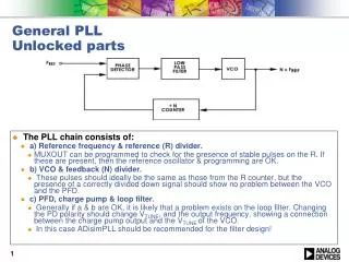
General PLL Unlocked parts. The PLL chain consists of: a) Reference frequency & reference (R) divider. MUXOUT can be programmed to check for the presence of stable pulses on the R. If these are present, then the reference oscillator & programming are OK. b) VCO & feedback (N) divider.

E N D
General PLLUnlocked parts • The PLL chain consists of: • a) Reference frequency & reference (R) divider. • MUXOUT can be programmed to check for the presence of stable pulses on the R. If these are present, then the reference oscillator & programming are OK. • b) VCO & feedback (N) divider. • These pulses should ideally be the same as those from the R counter, but the presence of a correctly divided down signal should show no problem between the VCO and the PFD. • c) PFD, charge pump & loop filter. • Generally if a & b are OK, it is likely that a problem exists on the loop filter. Changing the PD polarity should change VTUNE, and the output frequency, showing a connection between the charge pump output and the VTUNE of the VCO. • In this case ADisimPLL should be recommended for the filter design!
MUXOUT • Allows access to internal points of PLL chip. • CMOS output • Used for lock detect in most systems. • Used for production test in ATE. • Can be used to debug faulty circuits
Power-up and Initialization • On application of power to PLL synthesizers, the PLL counters are held in reset until a complete initialization is performed (generally speaking). • With correct power-up conditions and initialization, it should be possible at the very least to toggle between the DVDD and DGND modes. This will verify that power-up and programming conditions are working.
R counter • Reference divider or R counter takes the PLL reference and divides it to the PFD frequency. • Programming MUXOUT to R counter out allows us to check the stability of the R counter output. This verifies power supplies, programming and the REFIN source. • The scope output should be stable pulses, at the PFD frequency, with duty cycle = 1/R x 100% (exception div by 1). • Above example 100 MHz, divided by R = 4. 25 MHz frequency, 25 % duty cycle. • Scope probe may affect waveform. • Unstable pulses indicate too low a level of REFIN, or just a fault or noisy REFIN.
R counter pulses stable. • This means: • Part is powering up correctly. • Register programming is functional, and correct (for the R counter at least). • REFIN frequency and level is correct. • In ATE environment. Frequency error < 1 Hz indicates correct R counter functionality (using frequency counter). • Unstable pulses • Assuming voltage and programming are correct. • REFIN frequency is too high or too low • REFIN power level (or slew rate) inadequate. • REFIN too noisy. • Or could be problems with scope….
N counter • Locked N counter pulses will be stable. • Unlocked N counter output pulses will not be stable, but if present, indicate that the path between VCO output and the N counter output is correctly setup. • No N counter pulses indicate lack of VCO oscillation, or N counter fault. • Much smaller % duty cycle than R counter output (generally), since dividers are pulse swallow, and larger divider means smaller duty cycle.
N counters output, locked PLL. • Locked N counter pulses will be stable. VCO/N pulse, at PFD frequency. Above example Ndiv out = 25 MHz.
Unlocked N counter pulses will not be as stable, but will equal the VCO frequency divided by N.
PLL Debug • REFIN OK. • Power OK • VCO & N counter OK. • Phase Frequency Detector (PFD) & Low Pass Filter (LPF) need to be checked.
PFD / Charge Pump • In the previous steps, the PFD inputs from the R & N counter are present. • So the path between the PFD and VCO needs to be checked. • Ensure no short or open circuits are preventing the integration of the charge pump current pulses into a tuning voltage for the charge pump. • Simple check is to change PFD polarity from positive to negative and observe the VCO frequency changing. If it does not, then the charge pump may be faulty. • Check loop filter components. • Use ADIsimPLL to check that the phase margin is between 40 – 60° • Also check that the PLL loop bandwidth is < 10% of the PFD frequency. • Check that the appropriate charge pump current is used.
Low pass (Loop) Filter • Use ADIsimPLL to verify loop filter components. • PLL loop bandwidth should at a minimum be 0.1 x PFD frequency. 0.2 x PFD permitted in cases where Kv does not change. • Phase margin should be between 40 – 60 º. • < 40 º may be unstable and fail to lock correctly. • > 60 º may have very long lock times. • Difficult to test loop filter bandwidth and phase margin by experiment. Easier to simulate. • Ensure soldering connections are correct. No open or short circuits.
Case Study • Returned part for locking over temperature • Used with VCXO. • Returned to Failure Analysis. Passed ATE. • Setup in Apps lab. • Schematic examination showed high power coupling to RfinA pins. • Over temperature the high power level caused an N counter failure. • Reduced input power level solved problem.