CDR Preparation
CDR Preparation. Summary Sort of CDR Planning Human Resources Situation Feasibility Benchmarks. Summary.


CDR Preparation
E N D
Presentation Transcript
CDR Preparation Summary Sort of CDR Planning Human Resources Situation Feasibility Benchmarks
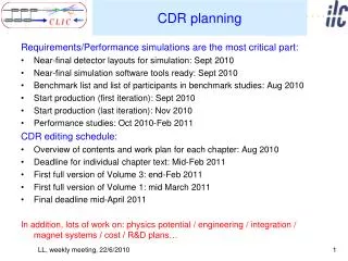
Summary The deadline for the CDR is imposed by management. The good argument is not to miss “the window of opportunity”. This dead-line is good, we should stick to it.A major change in approach to the CDR will result in a significant delay (2 years), a small delay will come by itself. There is no fully resource loaded planning for the achievement of the CDR and for the feasibility studies; but a) there is a very good estimate by the individual study leaders on what needs to be done until end 2010 and what can be done.b) progressively the resource holders (GLs in 3 accelerator departments) get involved in the elaboration of workpackages. There will not be any significant additional resources within the next 2 years. For the “feasibility items” so called benchmarks have been written down for the CDR. These benchmarks show target numbers to be achieved and they explain by what means they will be achieved. Additional results will come from:- input from the cost WG and technical follow-up- re-base lining of a few central technical choices- rebalancing of parameters (not more than factors 2...4)- many small individual studies in the equipment groups
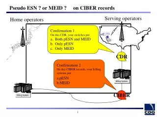
CLIC LTP Proposal MTP08 Int. Budget 09 Possible future MTPs MTP09 White Paper 2011-2014 Acc: 190 MCHF Det: 16 MCHF Technical Design (TDR) ? Conceptual Design Report (CDR)
Human Resources Situation (1/2) • CLIC budget 2009: 22 MSFR; approx 50% HR and 50% material • HR: About 8 MSFR for CERN staff plus 3 MSFR for temporary resources (=fellows, students, project associates…) • High fraction of CERN staff 100% allocated to CLIC study, but significant fraction (in particular recent newcomers) highly “partitioned” with other tasks. • The CLIC study team has started to involve progressively the group leaders into the CLIC project planning. Workpackages have been drafted (for 2010); discussions with GLs will still last for a couple of months.The drafted workpackages represent mainly a snapshot of the existing situation and only in a few cases the missing resources are documented.
Human Resources Situation (2/2) • CLIC budget 2010: 22 MSFR; approx 50% HR and 50% materialbasically (fortunately no dip!) the same as 2009. • 2010 will be the year of very active LHC commissioning; unlikely to receive significant additional CERN staff through redirection. • 2011 budget increase to 30 MSFR; HR department known not to be very reactive; additional resources will not be granted before 2011 + 6 months recruitment gap + training: additional resources end 2011 • Present collaborations are very valuable; their support will continue for the next 2 years.Potential of additional collaborations for CDR phase limited; recent new collaboration proposals aim at the TDR phase. The CDR at the end of 2010 will have to be prepared with the presently available resources.
Feasibility Benchmarks: Accelerating Structures End 2010 • Operate at least two accelerating structures with: • at an unloaded gradient above 100 MV/m • a 160 ns flat-top pulse with an appropriate beam loading compensation ramp • a measured breakdown rate in the range of a few times 10-7 /m • operation of a few thousand hours after conditioning • either the TD18, CLIC_G or equivalent design with an average a/λ ≥ 0.11 • equipped with high-order mode damping features • This will constitute the gradient feasibility demonstration. End 2012: • Operate at least five to ten accelerating structures with: • at an unloaded gradient above 100 MV/m • a 160 ns flat-top pulse with an appropriate beam loading compensation ramp • a breakdown rate in the range of 10-7 /m • operation of a few thousand hours after conditioning • CLIC optimized design, currently CLIC_G • with compact coupler • equipped with high-order mode damping features and load material • with all ancillary subsystems (cooling, vacuum) that are compatible with module integration • Life-time issues (fatigue) addressed either through rf design or material • Mechanical tolerances better than 5 µm
Feasibility Benchmarks: PETS (1/2) End 2010: • Operation of at least two more PETS in klystron-driven waveguide mode equipped with damping material (not necessary the final CLIC choice) and possibly different preparation technology (heat treatment for example): • Minimum 135 MW, up to at maximum165 MW power as a target • 240 ns pulse length • a measured breakdown rate in the range of a few times 10-7 /m • operation of a few thousand hours after conditioning of at least one of the PETS. • 20.8 A beam-powered test of a single PETS (without re-circulation) in the TBTS/CTF3 • 135 MW (with 28 A potentially available in CLEX, the peak power can reach 240 MW) • 140 ns total pulse length • A measured breakdown rate in the range of 10-4 or lower • Operation of a few hundred hours at 1 Hz • 7.4(10) A beam-powered test of a single PETS with external recirculation in TBTS/CTF3 • 135[CLIC nominal](81) MW circulating power, 65(65) MW [CLIC 3.0 nominal] available for accelerating testing • 250 ns total pulse length, 100(170 – CLIC nominal) ns flattish-top • A measured breakdown rate in the range of 10-4 or lower • Operation of a few hundred hours at 5 Hz • On/off/adjust will be demonstrated using the external reflection/recirculation system mounted on one of the PETS in TBL. • These tests taken together will constitute the PETS power production feasibility demonstration.
Feasibility Benchmarks: PETS (2/2) End 2012: 28 A beam-powered test of at least eight PETS in the TBL/CTF3 • 135 MW per PETS • 140 ns total pulse length • A measured breakdown rate per structure in the range of 10-4 or lower • Operation of at least one thousand hours at 5 Hz • Beam measurements to verify wakefield model • The test module foreseen in the framework of FP7 will not address feasibility issues for the PETS due to low power production capacity. • The ultimate PETS power performance (200 MW?). To follow the results obtained at the earlier stages, with improved design and technology if possible. • This will constitute the first major performance demonstration.
Feasibility Benchmarks: RF power through drive beam End 2010: Simulations: • Lattice design including cost optimisation options. • Study evidencing the decelerator stability with the current PETS. • Studies supporting that beam.based alignment of the decelerator is effective. • Some loss estimates for the decelerator • TBTS • Improved measurements of power and energy loss. Transverse kick measurements. • Measurements of dipole kicks. • TBL • The current schedule is to have 8 PETS installed as well as a spectrometer dump for energy spectrum studies, toward the summer 2010. This will allow to verify transport of a beam with up to 30% of the energy extracted.
Feasibility Benchmarks: RF power through drive beam End 2012: TBL It is foreseen to have 16 PETS installed in the TBL by 2011 and this will a allow to address a number of important issues relevant for the CLIC decelerator: Beam envelope increase due to dipole wake is predicted to be similar to the one for CLIC Decelerator alignment studies. Simulations show that even if TBL will not need advanced beam-based correction, the algorithms should still be effective. The TBL will therefore be a good testbed. Transport of a low energy beam (TBL space charge effects should be similar to CLIC, since the energy is lower by a factor 4 and the current is lower by a factor 3) Beam losses (halo generation) But limitations exist since even with 16 PETS we are limited to few betatron oscillations. Instrumentation and other hardware (movers) test-bed for the CLIC decelerator Simulations Further refinement of PLACET simulations. Items that are not estimated to be critical, should still be investigated before building large scale facilities. A non-exhaustive list is : Inclusion of real GdfidL wake function in the tracking simulations. Effects of of higher order wake fields, including dependence of the longitudinal mode on the transverse positions and effects of the quadrupole wakes. Effects of space charge. Effects of non-linear magnet multipole components.
Feasibility Benchmarks: Two Beam Acceleration End 2010:One PETS feeding one accelerating structure will be operated in the TBTS with a 28 A drive beam and 0.5 A main beam. The target performances are 132 MW generated power 140 ns total pulse length Accelerating gradient of 100 MV/m A measured system breakdown rate in the range of 10-4 or lower Operation of a few hundred hours at 5 Hz Breakdown kick measured System recovery demonstrated. End 2012: PETS and accelerating structures will be changed to the test-module configuration, and a second PETS/accelerating structure pair will be installed. This will allow the previous program to be repeated and refined and the running time extended.
Feasibility Benchmarks: Emittance Preservation(1/3) End 2010:Damping ring Updated reference lattice designs for the damping ring and pre-damping rings at 3TeV and 500GeV. Simulations confirming the damping ring performance in presence of intra-beam scattering. Simulations defining the requirement beam pipe surface properties to suppress electron cloud. The results of the world-wide collaboration on electron cloud suppression. Updated vacuum specifications to suppress the fast beam-ion instability. Prototype wigglers will be available. Simulations showing that the heat load in the wigglers is acceptable. A solution for the RF system including the beam loading compensation. RTML: Baseline lattices for the most important components with the exception of the spin rotator at 3TeV and 500GeV. A simplified model of the dynamic imperfections and feedback in the RTML for the integrated studies. Tolerances for dynamic imperfections (magnet jitter, dynamic magnetic fields). Assessment of the most important static imperfections in the RTML. Updated vacuum requirements for the RTML.
Feasibility Benchmarks: Emittance Preservation(2/3) End 2010:Main linac Lattice designs for 3TeV and 500GeV. Updated emittance preservation studies of the impact of the hardware performance at 3TeV and500GeV. A robust orbit feedback design. A study of the beam loading compensation scheme. BDS Updated reference lattice exists for CLIC at 3TeV. A lattice at 500GeV needs to be optimised for performance and machine protection. Studies establishing the performance of the collimation system. Studies establishing that the detector solenoid and shielding are acceptable. A tuning technique that removes the effect of static imperfections. A conceptual orbit feedback. A study of a tuning strategy that uses fast signals from the beam-beam collision. Post collision line A baseline design. Studies of the performance of the baseline design, in particular with respect to losses and the instrumentation potential. As this will be done by new members of the study, the work programme needs to be defined with them. Integrated studies A conceptual integrated feedback system will be developed for the beam transport from the damping ring to the IP. It will address the orbit and phase feedback. The RTML will be included in a simplified fashion. Studies evaluating the performance of the integrated feedback using the model provided by the stabilisation working group. A simplified integrated model of the longitudinal drive beam effects.
Feasibility Benchmarks: Emittance Preservation (3/3) End 2012: In general: The beam physics programme after 2010 will essentially focus on more indepth studies of the different effects mentioned above. BDS Test of the CLIC beam-based alignment scheme at ATF2. While the beam size that can be reached in ATF2 is 20nm, much larger than the 1nm for CLIC, ATF2 will serve as a test bed for the chromaticity suppression and the system tuning algorithms
Feasibility Benchmarks: Stabilization End 2010:Mechanical stability demonstration and assessment of Main beam Quad in CTF3.Mechanics optimized for passive damping. Gain of external feedback below 100. Final Stability will depend on environmental noise, which will have been modelled at that time.Meeting specification for MB Quad of 1nm rms above 1 Hz is probable. End 2012: Mechanical stability of a superconducting FF magnet at ATF2 measured.CLIC first design made; Mechanics optimized for passive damping. Gain of external feedback below 100. Severe specifications in terms of noise reduction will result for the physics detector.Meeting specification of 0.18 nm is challenging and unlikely. Mitigation path using different supporting structures will have been evaluated.
Feasibility Benchmarks: Machine Protection End 2010:Full inventory of failure modes, simulation of their impacts on the accelerator structures Detailed requirements for passive machine protection. Evaluation of the requirements for beam observation systems to detect the onset of instabilities in drive and the main beam (i.e. beam loss, beam intensity loss, position and emittance). Proof of feasibility for magnet power circuits with guaranteed tolerance for 2 ms after the onset of failure. Required tolerance for all magnet circuits for safe operation with nominal beams. Establish the procedure to reach nominal CLIC operation starting from a “cold” machine, based on successive beams of increasing intensity and brilliance. Evaluate the unavailability of the machine for nominal operation due to various interlock conditions and equipment failures. End 2012: Complete and validated design of passive protection system. Detailed scenario for machine protection checks Detailed design of “next beam permit” machine protection system for slow failures.