Download
1 / 14
140 likes | 174 Vues
Understand the importance of thermal QA for planks, utilizing infrared thermography and fault analysis to ensure performance and reliability. Learn about thermal measurements, FEA thermal modeling, and detecting faults for optimal results.

E N D
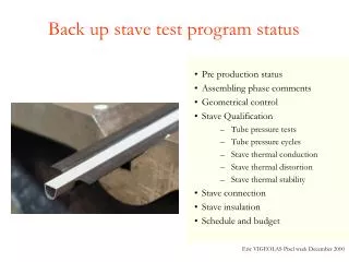
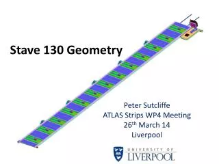
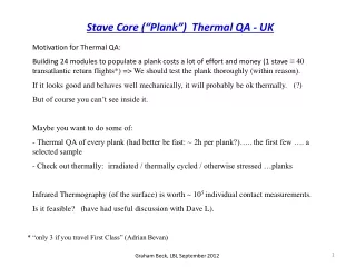
Stave Core (“Plank”) Thermal QA - UK • Motivation for Thermal QA: • Building 24 modules to populate a plank costs a lot of effort and money (1 stave ≡ 40 transatlantic return flights*) => We should test the plank thoroughly (within reason). • If it looks good and behaves well mechanically, it will probably be ok thermally. (?) • But of course you can’t see inside it. • Maybe you want to do some of: • Thermal QA of every plank (had better be fast: ~ 2h per plank?)….. the first few …. a selected sample • Check out thermally: irradiated / thermally cycled / otherwise stressed …planks • Infrared Thermography (of the surface) is worth ~ 105 individual contact measurements. • Is it feasible? (have had useful discussion with Dave L). * “only 3 if you travel First Class” (Adrian Bevan) Graham Beck, LBL September 2012
IR Thermography At low T: -30C black body radiation intensity is still appreciable: ~ 40% room temperature level. The peak is well within the LWIR window, commonly used by the cheaper IR cameras* (e.g. QMUL, Liverpool)! Energy Balance + Kirchoff says that: emissivity + reflectivity + transmissivity = 1. =>Thermography works best on high emissivity surfaces: • Bigger signal • Lower reflected ambient radiation (inc. camera!) • The (default) plank surface is 25mm Kapton over (refective) Aluminium shield (if present). Kapton is somewhat transmissive. • For bus tape e I measure ~ 90% (above room temperature); DaveL measures ~83% at low T (-25C?). • Expect plank thermography can work. • Sensitivity to faults will depend on the “noise” due to surface quality – uniformity, flatness etc. • Even if the bus gets buried (?) there should be an electrically insulating (so high e) surface. * Nowadays you can buy a radiometric IR camera for ~ 4 transatlantic flights (10% of a stave). Graham Beck, LBL September 2012
How would you make a measurement? • Flow coolant through the pipe, at ~ -30C. • Actively heat the plank? It turns out that natural convection and radiation from ambient supplies about the right thermal load. Rough estimates: Convection: Assume htc = 5W/m2K (consistent w. R.Bennett calculations and Geneva experiments). (ignore dependence on plank orientation here). Radiation: W/A = e. s * (T4 – Ta4) A=Area, Stefan’s constant s = 5.67E-8, e =emissivity: assume = 1 ≈ 4s .Tmean3 * DT ; (DT << T) i.e. (linear approx). Radiative htc ≈ 4s.Tmean3 e.g. +20C (ambient) => -25C (Tmean ≈ 270K) => 4.5 W/m2K - very comparable to convection! Ambient load per module length of plank: ≈ 125 mm × 98mm × ~ 10 W/m2K × 45C => 5.5W ≈ Hybrid Power. Graham Beck, LBL September 2012
FEA Thermal Model of a section of plank +20C, 10 W/m2K Surface Film Load • Quick & Dirty: Stave130 Module FEA with sensors+hybrids stripped away. Fast and informative … not particularly accurate ! • Same htc top & bottom (clearly inaccurate) • Cable Bus top and bottom • 2mm id Ti pipe. • Material Specific Heats assigned (used in transient case) - but Facing Glue Cv omitted. - Corresponds rather roughly to Tim’s planklet measurement : Graham Beck, LBL September 2012
- 25 ° C ° - 32 C - 25 ° C PERFECT PLANK in STEADY STATE: comparison with Tim’s IR plot. After a couple of iterations to tie down CO2 temperature (approx. -38.5C) (FEA Ambient Thermal Load now ~ 6.5W). ABAQUS FEA Tim’s IR (Stavelet3+masking tape) & Fit Scale: Abaqus DT looks ~ 14% low. => Some confidence in FEA feasibility studies … Graham Beck, LBL September 2012
Now introduce a FAULT into the FEA model: GLUE missing between the foam and pipe Effect on STAVE (module) performance: Mean TC Headroom Sensor T (degrees) Baseline, No faults -25.23 C 21.6 Missing from one pipe, top half, DZ 10mm -25.21 21.5 " " " DZ 30mm -25.14 21.3 " FULL circumference, 30mm -24.6 19.7 • Choose as a benchmark test: glue missing over 30mm length, half the pipe circumference. • Has only a small effect on STAVE thermal performance (heat spreads around the fault) • Maybe you would want to know about it anyway. It might deteriorate with thermal cycling, etc. Graham Beck, LBL September 2012
PLANK FEA: GLUE FAULT (STEADY STATE) Plotted bands: -32C=> -36C 0.2C intervals (~ camera resolution) Height of bump is 0.7C (top surface - also 0.4C bump on bottom surface) Would this be visible in practice? - depends on “noise”: bus surface flatness, uniformity, convective fluctuations etc. Graham Beck, LBL September 2012
Now look at Transient behaviour … Tim, re Thermal Shock: “What is the typical dT/dt seen during Stavelet Testing with CO2?” Stavelet 3: IR temperature history of two points on the surface, above the pipes, after turning on CO2 (later turning off / back on again) • At SP02 (above inlet pipe) T falls ~ 7C/s after turning on CO2… • CO2 flows around U-bend, and reaches SP01 after ~43s => speed ~ 12mm/s. • meanwhile, outlet (SP01) is cooled, slowly, by conduction across the plank. • (Interesting? ~simultaneous warming when flow stopped). Try to reproduce this in FEA - then assess potential for fault finding . . . Graham Beck, LBL September 2012
Propagate change from Ambient to CO2 conditions in 1s steps Transient FEA… Sledgehammer approach: • Divide pipe surface (crudely!) into 8 x 12.25mm lengths along Z • Transient FEA 1s increments: • Change film conditions for successive sections (≡ 12.25mm/s) from +20C, 10W/m2K => -38.5C, 8000W/m2K. • Apply this to inlet pipe. • After 43s, apply (in reverse sense) to outlet pipe • Allow to settle (a further 43s). (See Perfect Plank Transient.wmv: !Range is +20C to -40C) => Plot history of surface T above centre of each pipe (as Tim) Graham Beck, LBL September 2012
PERFECT PLANK: Surface Temperature transient. Rate [C/s] vs time T vs time FEA: FEA doesn’t reproduce all features of IR, and peak dT/dt is 70% higher But worth pursuing … IR: Graham Beck, LBL September 2012
FEA TRANSIENT – with and without GLUE FAULT T vs time Rate [C/s] vs time PERFECT FAULTY (see Faulty Plank Transient.wmv Range: 0C to -40C) Peak Rate is unchanged on inlet side (~11C/s), but ~25% lower over centre of fault. Graham Beck, LBL September 2012
A Trivial QA Algorithm:• Define lines L1,L2 on the surface above the pipes. • Record T on L1, L2 for duration of test (this would be ~ 5 mins for a full stave) • For each Z, evaluate dT/dt(t). • Plot Peak dT/dt vs Z. • Look for anomalies (bumps)The plots are derived in this way from the FEA Temperatures at 2x20 nodes along the bus tape.[Fluctuations due to jerky FEA! Ignore Z extremes – wrong BCs!]=> Inlet behaviour is fairly level. . .=> Outlet shows expected bump due to fault. So there is an appreciable signal !! . . .BUT . . . . . . there will be background conduction from ± Z . . .and what is the noise like in practice???Many Questions: Best answered by experiment! Graham Beck, LBL September 2012
Alternative (avoiding thermal feedback) - FLOW routed through independent chiller bath - RETURN from stave routed directly to Vaporiser (Poss.re-locate second valve). T1 T2 STAVE CYLINDER T3 T4 Tn located as per Nikhef Manual. T4 redundant if HEX omitted. T5 could be un-monitored/low precision. T1,T2,T3: 4-wire PT100? (expensive but accurate). OR Pico 8-chan. Thermocouples (incs. Labview) Vaporiser (Heater) Dial + DAQ. (Re-locate upstream of vaporiser) T5 QMUL will build a CO2 blow-off cooling system to evaluate these QA ideas (so far have a list of parts to purchase – but need a decision on temperature monitoring)...and I believe Oxford are building an intentionally “faulty” stave. Graham Beck, LBL September 2012
coverlayer bus tape BACKUP: Measurement of IR Emissivity of Bus Tape Bus sample + thermal grease on (warmed) block of copper. Black tape added (v. small correction to T, estimated by adding more layers). Spot radiometer measures T of tape and bus: Bus e estimated assuming 94% for black tape. - e seems high – as hoped. Note: Kapton thickness is 25mm, cf radiometer sensitive in 8-13mm window. At low temperature (-25C?) , Dave Lynn finds ~ 83%. Graham Beck, LBL September 2012