THIN FILMS FOR CLIC ELEMENTS
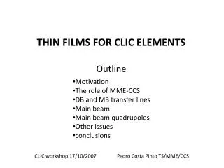
THIN FILMS FOR CLIC ELEMENTS. Outline. Motivation The role of MME-CCS DB and MB transfer lines Main beam Main beam quadrupoles Other issues conclusions. CLIC workshop 17/10/2007 Pedro Costa Pinto TS/MME/CCS. THIN FILMS FOR CLIC ELEMENTS. Motivation.

THIN FILMS FOR CLIC ELEMENTS
E N D
Presentation Transcript
THIN FILMS FOR CLIC ELEMENTS Outline • Motivation • The role of MME-CCS • DB and MB transfer lines • Main beam • Main beam quadrupoles • Other issues • conclusions CLIC workshop 17/10/2007 Pedro Costa Pinto TS/MME/CCS
THIN FILMS FOR CLIC ELEMENTS Motivation Changes in the vacuum requirements for CLIC: In 2006: “dynamic vacuum should be 1x10⁻⁸ mbar, static vacuum 1-5x10⁻⁹ mbar“ https://clic-meeting.web.cern.ch/clic-meeting/2006 In 2007: “whispers” of about 1x10⁻¹⁰ mbar for the main beam (MB) near the intersection point and for the transfer lines (MB and DB). For the MB: high luminosity => high electrical field => ionization of the residual gas by tunnel effect => ion induced desorption (IID) => instabilities. For the transfer lines: high current => ionization of the residual gas by collision => ion induced desorption => instabilities. Not yet fully studied. Need confirmation from simulations. Anyway, “always better than 10-8 for the main beam...”
THIN FILMS FOR CLIC ELEMENTS The role of MME-CCS CCS has expertise in surface analysis, surface treatments and thin film coatings for UHV applications. induced desorption, (by photons, electrons, ions), is a surface phenomena. This expertise can be (and has already being) used to find solutions for surface’s related problems.
THIN FILMS FOR CLIC ELEMENTS DB and MB transfer line Total length: 2x 21km 2% filled with 1m long magnets: 2x 420 magnets Diameter of the beam pipe f=40mm Limit pressure to avoid ion stimulated desorption: 10-10 Torr (“large” molecules) Pressure profile in a tube with uniform distributed outgassing P Pmax Vacuum pump Vacuum pump Ppump x q -> outgassing rate R -> radius of the tube Lhalf tube -> length of half tube S -> pumping speed C -> conductance of half tube L=2Lhalf tube
THIN FILMS FOR CLIC ELEMENTS DB and MB transfer line Total length: 2x 21km 2% filled with 1m long magnets: 2x 420 magnets Diameter of the beam pipe f=40mm Limit pressure to avoid ion stimulated desorption: 10-10 Torr (“large” molecules) Static vacuum L [m] L [m] q [Torr.l.s-1.cm-2] S [l.s-1] 40 1.7 2.3 No bakeout: main gas H2O 1.4.10-12 46 5.0 6.8 With bakeout: main gas H2 5.10-13 Possible solution… 36 9.6 14 With bakeout: CO 5.10-14 28 814 1220 With NEG: not pumped CH4 10-17 Better solution 6 1202 1802 With NEG: not pumped Kr 2.10-18
THIN FILMS FOR CLIC ELEMENTS DB and MB transfer line Total length: 2x 21km 2% filled with 1m long magnets: 2x 420 magnets Diameter of the beam pipe f=40mm Limit pressure to avoid ion stimulated desorption: 10-10 Torr (“large” molecules) Why NEG coating solution better than bakeout? Without NEG, desorbed molecules will follow random walk movement until being pumped by localized pumps (extremities of the beam pipe) With NEG, the pumping power is right there! pressure recovering time is much shorter. DB and MB transfer lines seams feasible with actual technology.
THIN FILMS FOR CLIC ELEMENTS Main Beam Bakeout excluded: tight mechanical tolerances. Pumping speed in the accelerating structures is limited If 10-10 torr are necessary… this is a feasibility issue for CLIC! Dynamics of the H2O pumping in limited conductance systems must be better understood • An experimental set-up is being implemented to study H20 pumping dynamics Best possible dynamic vacuum must be simulated • Pumping speed and geometry • Thermal desorption/adsorption rates • Surface coverage vstime • Ion desorption yields • Ionization efficiency per train • Ion bombardment of the walls • Breakdown rate • Gas released per breakdown • ……………………………………… We propose monte carlo and electrical network analogy approach
P PL/2 stainless steel Ppump 0 L/2 L x L=1000mm f=5.6mm THIN FILMS FOR CLIC ELEMENTS Main Beam quadrupoles length: ~1-2m Diameter of the beam pipe ~5-6mm Limit pressure to avoid ion stimulated desorption: 10-10 Torr (“large” molecules) Bakeout excluded: temperature of the magnets < 80oC q(h)= qlimit+ q1h . t-1 Non baked stainless steel: q1h=10-9 Torr.l/s/cm2 What about qlimit? Depends on H2O desorption-adsorption dynamics Effects of beam conditioning?...
THIN FILMS FOR CLIC ELEMENTS Main Beam quadrupoles length: ~1-2m Diameter of the beam pipe ~5-6mm Limit pressure to avoid ion stimulated desorption: 10-10 Torr (“large” molecules) T. Zickler CLIC module working group meeting #21-2007 Distributed pumping is required With actual technology: Antechamber with active pumping elements (NEG coating or strip, sublimation pump) Beam pipe Pumping: NEG , Sublimation pump Antechamber Probably not a feasibility issue
THIN FILMS FOR CLIC ELEMENTS Main Beam quadrupoles length: ~1-2m Diameter of the beam pipe ~5-6mm Limit pressure to avoid ion stimulated desorption: 10-10 Torr (“large” molecules) T. Zickler CLIC module working group meeting #21-2007 Distributed pumping is required And If we find a lower activation temperature NEG? The NEG film will be applied directly in the beam pipe. Beam pipe NEG thin film
THIN FILMS FOR CLIC ELEMENTS Other issues Combining rings • High levels of synchrotron radiation => high photon induced desorption • Requires high distributed pumping speed • NEG coatings are widely used in electron storage rings for synchrotron light sources. (ESRF, Elettra…) • More details are necessary to evaluate situation. not a feasibility issue injection lines • VERY low secondary electron yield (SEY) required (0.9... maybe…) • CCS is launching a program to develop new materials with low SEY. Nitrides, carbides and borides of transition metals, C:N and other carbon based materials will be studied. feasibility issue
THIN FILMS FOR CLIC ELEMENTS Conclusions • MB and DB transfer lines: 10-10torr feasible with bakout or NEG. (NEG better for dynamic vacuum). Not a feasibility issue. • Main beam: 10-10torr not possible without heating the structures. Best possible dynamic vacuum must be simulated. H2O behavior must be studied. • feasibility issue. • Main beam quadrupoles: distributed pumping required. Probablynot a feasibility issue. • Combining rings: classical NEG solution. Input is necessary to correctly evaluate the situation. Not a feasibility issue. • injection lines: maybe a SEY of 0.9 is required. feasibility issue. acknowledgments Bernard Jeanneret and Daniel Schulte.
THIN FILMS FOR CLIC ELEMENTS CO pressure evolution in an 30GHz HDS structure
THIN FILMS FOR CLIC ELEMENTS Pumping distribution in 30GHz HDS structure
THIN FILMS FOR CLIC ELEMENTS Introduction Brief overview of the outgassing in UHV systems Thermal outgassing: Driving force: thermal energy. Non baked systems: mainly H2O baked systems: mainly H2 Outgassing rates But also CO, CO2 , CH4 … Stimulated outgassing:
THIN FILMS FOR CLIC ELEMENTS Introduction Brief overview of the outgassing in UHV systems Thermal outgassing: Driving force: thermal energy. Non baked systems: mainly H2O baked systems: mainly H2, but also CO, CO2, CH4 at lower rates Stimulated outgassing: Driving force: particles striking the surfaces of the system (photons, electrons, ions) Strongly dependent baked systems: mainly H2, but also CO, CO2, CH4 at lower rates
THIN FILMS FOR CLIC ELEMENTS Introduction Combination rings: synchrotron radiation => high photon stimulated desorption DB transfer line: Ions created and trapped inside trains; between trains ions are released and strike walls => ion stimulated desorption MB transfer line: Roughly the same as DB transfer line Main beam: Near the interaction point beam’s electrical field is enough to ionize residual gas => ion stimulated desorption
THIN FILMS FOR CLIC ELEMENTS DB and MB transfer line Total length: 2x 21km 2% filled with 1m long magnets: 2x 420 magnets Diameter of the beam pipe f=40mm Limit pressure to avoid ion stimulated desorption: 10-10 Torr (“large” molecules) And for the magnets? • if Tmax=200C ok for existing NEG • If not, hybrid solution! Uncoated beam pipe NEG coated beam pipe NEG coated beam pipe pump pump
THIN FILMS FOR CLIC ELEMENTS Main Beam quadrupoles Bakeout excluded: tight mechanical tolerances.
THIN FILMS FOR CLIC ELEMENTS Main Beam quadrupoles length: ~1-2m Diameter of the beam pipe ~5-6mm Limit pressure to avoid ion stimulated desorption: 10-10 Torr (“large” molecules) T. Zickler CLIC module working group meeting #21-2007 Distributed pumping is required Beam pipe Pumping: NEG coating Sublimation pump Antechamber