Download
1 / 29
290 likes | 332 Vues
Learn about thin films technology for RICH detectors, including functionality, production technologies, and performance. Presented at the CBM-RICH workshop, this covers coatings like anti-reflective and reflective coatings, protection enhancements, and reflectivity optimization for detectors. Discover the use of metallic reflectors, adherence, barrier layers, and substrate materials. Explore the application of multi-dielectric reflective coatings and anti-reflective coatings for improved performance.

E N D
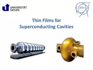
Thin films technology for RICH detectors André Braem, CERN, PH-DT2 department Functionality Production technologies Performance Presented at the CBM-RICH workshop 06-07 March 2006
Anti-reflective coating(T 92% ~98%) Photocathode(QE ~25%) Reflective coating (R~90%) Wavelength shifter Thin films in RICH detectors The light yield is directly proportional to the performance of the coatings
Reflective coatings Protection and reflectance enhancement dielectric layers Metallic reflector Adherence and barrierlayer Substrate(glass, Be, plastics…)
Al + MgF2 glass A B Al + MgF2 C Cr + SiO Au glass Al + MgF2 Au glass Adherence and barrier under-layer A thin (~20nm) layer of Chromium or Nickel is generally used to promote adherence on most substrates. A barrier layer (SiOx, CrOx…) is mandatory when the substrate material risks to react with the metallic reflective layer. Inter-diffusion of aluminum (reflective layer) and gold (replicated substrate) : Cr + SiO diffusion barrier (CF mirror of CERES inner RICH) 2 months at 100˚C :
Metallic reflective coatings Aluminum is the best metallic reflector for a broad band reflectivity in the far UV. 220 < l < 600 nm R~90% in VUV the reflectivity of aluminum is strongly dependent on: - The production parameters such as vacuum quality, deposition rate etc.. - The substrate roughness (<1.5nm rms) - The surface oxidation a protective layer is required. Magnesium fluoride is commonly used as single protective layer for VUV mirrors “Standard” VUV coatings for Cerenkov detectors: DELPHI, CERES, HADES, COMPASS…
photons qinc. high index low index high index n pairs LH low index Al reflector Cr adherence layer substrate Metal multi-dielectrics reflective coatings Reflectivity enhancement at given wavelength by exploiting interferences Aluminum over coated with n pairs of transparent films of high (H) and low (L) refractive index. Dielectric films like SiO2, MgF2 (L-materials) or HfO2, Nb2O5, TiO2 (H- materials) are used. Hard mirror surface can be achieved good mechanical protection Technology limited for l > 220nm due to the lack of H-materials which are transparent in VUV.
Metal multi-dielectrics reflective coatings Simulated reflectivity of aluminium + pairs of SiO2 – HfO2 layers optimized for l = 300nm
620 413 310 248 206 Measurement Simulation <HPD QE,(2-6 eV)> = 0.176 <HPD QE · R2 (2-6 eV)> = 0.149 Reflective coating optimized for LHCb RICH2 Detection efficiency of an HPD detector (quartz window), with and without double reflection from the coated mirror, qinc. = 30º. Reflectivity of Al + 1 pair SiO2/HfO2 on glass, qinc. = 30º l [nm] Absorbance in HfO2 film !
Anti reflective single layer coatings MgF2 is generally selected for single layer broad band AR coatings On quartz: Optimum n1 = 1.22 ! n MgF2 (250nm) =1.412 ! The surface reflectivity is reduced by a factor 2. Best performance if Low refractive index (1.2 < n < 1.4) can be obtained with porous sol gel silica coatings.
Anti reflective multi-layers coatings Pairs of low and high refractive index materials Many solutions are available in coating industry for UV-VIS light. Low residual reflectivity but in a reduced band width !
Coating technology Metals and dielectrics are evaporated in a high vacuum deposition plant. Substrate (rotation) Thickness monitor Dielectrics are evaporated from an electron gun source Aluminium is evaporated from a Tungsten filament
Deposition parameters Layer Rate [nm/s] Thickness [nm] Pressure [mb] Cr 0.2 10 1x10⁻⁷ Al >20 85 2x10⁻⁷ MgF2 1.5 311 2x10⁻⁷ SiO2 0.2 382 2x10⁻⁵ (O2) HfO2 0.2 282 2x 10⁻⁵ (O2) 1 Optimized for l=160nm 2 Optimized for l=275nm Well known technology available from most industrial partners - Substrate roughness • Residual pressure • Aluminium deposition rate • Delay between Aluminium and MgF2 depositions But for optimal reflectivity in VUV some critical parameters must be well under control:
Series production of mirrors for LHCb RICH2 @ CERN Average reflectivity (250-350 nm)
lnm 250 225 207 190 183 175 155 Meas. PM Ref. PM VUV monochromator D2 lamp Rotating mirror VUV reflectivity measurements Essential for the production of VUV mirrors !
h h e- e- Photocathodes for RICH detectors 1). Alkali halide in gas photodetectors- Large area CsI reflective photocathodes- Sensitive in the 7.75 - 6.2 eV range- Robust and transferable (in moisture free environment) 2). Bi-alkali Antimonide in vacuum tubes- Semitransparent encapsulated photocathodes- Sensitive in the 2 – 4 eV range (K2CsSb + UV extended glass window)
detector assembly & operation PCB production CsI deposition PC transfer & storage Focusing electrodes Photocathode processing Operational photon-detector Silicon sensor FE electronics Vacuum seal Photocathodes for RICH detectors CsI PC:coating under vacuum and detector assembly under gas HPDs :PC and detector assembly inside vacuum chamber • Need state of the art technologies (UHV, chemistry, thin film coating, vacuum sealing, encapsulated electronics)
pcb substrate protective box CsI Photocathodes production Vacuum evaporation of CsI powder from 4 sources. Thickness monitor PCB substrate 4 CsI sources + shutters Uniform deposition of 300 nm CsI Deposition rate: ~1nm/s Substrate temperature: 60˚C Pressure ~6 x 10⁻⁷mb Heat post-treatment: 60˚C , 8-12hrs CsI PC transferred in a protection box under Argon atmosphere after quality control Remote controlled enclosure box
CsI photo-current measurements Photo-current scan on PC46: Mean value <Inorm> = 3.71 min-max variation 6% QE obtained from test beam measurement on 6 CsI PCs All CsI data from H.Hoedlmoser CERN ALICE/HMPID
Initial current level before heat enhancement phase Current level after enhancement phase Series production of CsI PCs
Development of HPD vacuum tubes at CERN 5” HPD 10” HPD h Bi-alkali photocathode e- dV = 20kV Ee = 20 keV Si sensor Indium joint In silicon: 3.6eV 1 e/h pair 20keV 5000 e/h Front end electronics Spherical HPD PET HPD
Turbo Pump The HPD development plant “External” photocathode process Ultra-high vacuum technology
Performance of bi-alkali photocathodes QE of a K2CsSb photocathode (HPD PC87) Radial dependence of HPD (PC68) QE for =230, 290 and 350 nm.
Wavelength shifters coatings • P-Terphenyl: Absorbtion range 110-360 nm ; emission peak at 385 nm • A dedicated plant has been set-up for coatings on PMTs Vacuum evaporation from a molybdenum crucible: Pressure ~5x10⁻⁵ mb Thickness >1 mm Rate > 10 nm/s Vaporization temp. < 200˚C • Weak mechanical resistance A protective layer of 30nm MgF2 is required ! Inhomogeneous coatings on glass surfaces Alternative coating method: Solvent spray with transparent binder
Performance of P-Terphenyl Publication of G.J.Davis NIM B 117(1996) 421-427 P-terphenyl evaporated at pressure of 1-1.5 x 10⁻¹ Torr Deterioration in efficiency of p-terphenyl after a six month period (175 nm incident light) External QE of p-terphenyl at ~optimal thickness Ext. QE: Nph emitted (4p) / Nph incident
Summary and conclusions Functional coatings play an important role at various places in a Cherenkov detector. The light yield is directly proportional to the performance of the coatings. Coatings exist for high reflectivity, Anti-reflection, photosensitivity and Wavelength shifting. For detectors in the visible/near UV range standard industrial solutions are available. For applications in the far UV / VUV technical challenge and cost increase drastically. Reliability and long term stability become issues. The light yield is directly proportional to the performance of the coatingsCoatings exist for high reflectivity, AR, photosensitivity, WLSFor detectors in the visible/near UV range standard industrial solutions exist.For applications in the far UV / VUV technical challenge and cost increase drastically. Reliability and long term stability become issues.
PC current reading D2 light source +100V Translation stage PM Reference CsI PM CsI quality control: VUV-scanner 2d scan of photo-current across the whole photocathode Relative measurement to a reference CsI photomultiplier
Heat post-treatment • CsI deposition performed at 60°C • All PCs have similar initial response • Heat post treatment at 60°C for 24hrs • The PC response increases 20-50% during the first hours.
Heat post-treatment Decreasing response observed on some PCs ! The presence of residual water in the vacuum chamber is believed to strongly influence the photo-emission properties of the highly hygroscopic CsI film !