Download
1 / 25
250 likes | 276 Vues
This paper discusses the progress in the development of RF systems for fusion devices, focusing on long pulse operation and integration challenges. It also presents experimental results from Tore Supra and explores RF techniques and developments for LHCD power upgrade and the design of a ITER-like ICRH antenna.

E N D
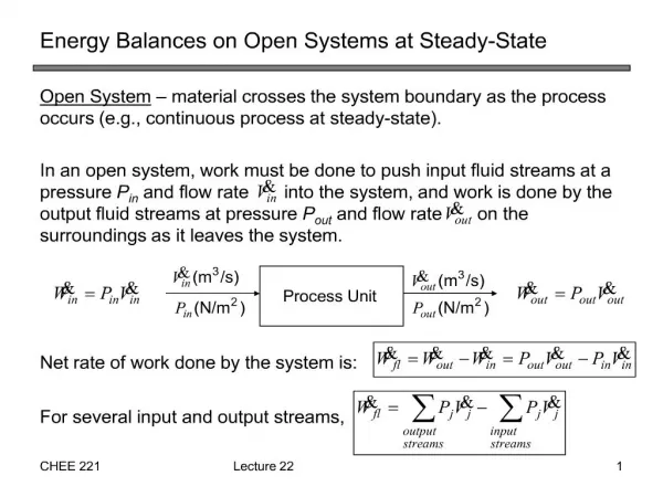
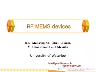
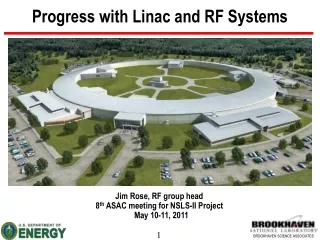
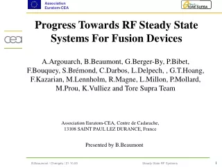
Progress Towards RF Steady State Systems For Fusion Devices A.Argouarch, B.Beaumont, G.Berger-By, P.Bibet, F.Bouquey, S.Brémond, C.Darbos, L.Delpech, , G.T.Hoang, F.Kazarian, M.Lennholm, R.Magne, L.Millon, P.Mollard, M.Prou, K.Vulliez and Tore Supra Team Association Euratom-CEA, Centre de Cadarache, 13108 SAINT PAUL LEZ DURANCE, France Presented by B.Beaumont
Introduction • RF systems are widely used on magnetically confined fusion experiments. • Developments during many years have produced RF systems which have supported the progress of plasma performance and opened up new areas of investigation. • For the next step devices, long pulse operation is essential and it is a new challenge for the integration of the RF systems. They have to be highly reliable, with built-in strategies to recover from trips and breakdowns.
A selection of recent Tore Supra experimental results System integration RF techniques developments and R&D LHCD power upgrade, ITER-like ICRH antenna Antenna studies Example of RF design for ITER : in-port matching ICRH antenna Conclusion Outline
A selection of recent Tore Supra experimental results System integration RF techniques developments and R&D LHCD power upgrade, ITER-like ICRH antenna Antenna studies Example of RF design for ITER : in-port matching ICRH antenna Conclusion Outline
The progress in term of RF assisted discharges can be expressed in the domain Energy/Duration. Recent experimental work is focused on : Combined operation of RF systems : The high power & performance quest Interaction studies : try to live together Identify and study specific issues : Heat : Private heat flux, local RF losses, heat flux from other antennas, limiter connections, Protons impacts… + for ITER : shadowing of blanket modules, a's contributions…, NB shine through… Coupling : Plasma/antenna distance, location of fuelling, pellet injector, relative antenna radial positions,… Local enhanced RF fields .. Even far from antennas 2 MW After the 20th IAEA 8 MW 2001- the 20th IAEA Tore Supra Exp. Results
ICRH+LHCD Multi-MW MW Ptot PICRH • Simultaneous use of multi-frequencies RF heating/CD systems(ICRH, LHCD, ECH) • Power level in excess of 10 MW, mainly ICRH,during pulses lasting up to several tens of resistive times • 9MW of ICRH coupled to plasma sustained by LHCD is safe condition required for continuous operation • 4MW/one minute ICRH pulse in LHCD (3MW) plasmas Line density (1019m-2) PLH Ip (MA) Stored energy (MJ) keV Te(0) Ti, @r/a=0.2 shot 33612, Combination of ICRH (57 MHz - 8.5 MW) and LHCD (3.7 GHz -1.4 MW). (R=2.4m, a=0.72m, Ip= 0.9MA, BT=3.7T)
Safety Control loops IR image of IC antenna, at t = 63.7s, in a combined ICRH (4MW)/LHCD (3MW) discharge • Various hot spots on the ICRH antennae are identified • 1: sensitive to the total power • 2: mixed total IC power and private IC power • 3: sensitive to LH power only • 4: predominantly private IC power • input for RT Controls & Algorithms • Reality is far from the classical ln & lq theory. Large peaking of heat fluxes: • governing the temperature and the coupled power • inducing shear stress in the components -> CFC !
A selection of recent Tore Supra experimental results System integration RF techniques developments and R&D LHCD power upgrade, ITER-like ICRH antenna Antenna studies Example of RF design for ITER : in-port matching ICRH antenna Conclusion Outline
System integration Successful operation of RF systems depends on integration in Tokamak system : Arc protection / RF diagnostics / matching reliability discrimination (cross-talk) Response time Power controls Current balance control Array phase control Power Ramp-up balance RT control loops (internal and external to RF syst.) Recovery after trip : strategy (reduced power, counters, …) on/off solid state switch Degraded mode of operation part of antenna missing => Stresses=> power limit maintenance schemes Long process : Trial and errors Water leaks… Breakdowns… Improvements Time…
A selection of recent Tore Supra experimental results System integration RF techniques developments and R&D LHCD power upgrade, ITER-like ICRH antenna Antenna studies Example of RF design for ITER : in-port matching ICRH antenna Conclusion Outline
RF developments • Tore Supra is exploring long duration plasmas • Plasma size (a~0.7m) : need for non inductive CD • Large operational domain = large power • Large power = appropriate PFC and controls • Highest efficiency for volume CD is LHCD • On going upgrade of LHCD system to 8MW: • New LHCD launcher • New high power CW klystron • ITER support : • New TS LHCD launcher is ITER-like Design • ITER-like ICRH antenna
A selection of recent Tore Supra experimental results System integration RF techniques developments and R&D LHCD power upgrade, ITER-like ICRH antenna Antenna studies Example of RF design for ITER : in-port matching ICRH antenna Conclusion Outline
CIMES LHCD upgrade 500 kW CW Mock up • High power CW klystron development with TED: • Target = 700 kWCW on VSWR=1.4 any phase (and 750 kW on matched load) • 5 years effort nearing completion: • Large collector (~1600kW beam power) • 2 windows output circuit +recomb. circuit • Diode type klystron • Prototype has delivered 700kW on load during several hours • problem on geometry assembly faulty brazing suspected (under investigation) • Lessons from this R&D program: • Close collaboration with supplier essential • Intermediate tests to validate sub components and steps mandatory. Specific field => Dedicated test beds
LHCD upgrade • Passive/Active Multijunction Launcher: • Large cooling efficiency • Target n//= 1.72 +/- 0.28 @ +/- 90° • CW power ~3MW at 25 MW/m² • 200 waveguides in total, 16 RF inputs (windows) • 3 years fabrication inc. Specific R&D • Lessons from this R&D program • Example of plug antenna (like all TS antennas) • Integration of many different components & contracts • Firms are very skilled…until they have to do the real thing • stop points on brazing, material procurement,… • Specific R&D performed on explosion bonding • Tests and samples essential (as usual) Stainless steel 1.82 mm Copper
A selection of recent Tore Supra experimental results System integration RF techniques developments and R&D LHCD power upgrade, ITER-like ICRH antenna Antenna studies Example of RF design for ITER : in-port matching ICRH antenna Conclusion Outline
X I c1 1 X c3 I I 3 a I R b s V a k R t s V b X s X s k p k p R s R s k X t s I X 2 s X I c2 4 X c4 jXc1 Rin+jXin I1 R0 I2 Ifeed Rin+jXin jXc2 ITER like ICRH Antenna Conventional Conjugate-T concept = ITER Relevance : ELM Resilient Antenna • First experiments in 2003 • Faraday shield modified to reduce coupling • Experiments in end 2006/2007 with improved current control loops
A selection of recent Tore Supra experimental results System integration RF techniques developments and R&D LHCD power upgrade, ITER-like ICRH antenna Antenna studies Example of RF design for ITER : in-port matching ICRH antenna Conclusion Outline
RF loads 3 dB coupler TE10-TE30 Mode Converter PAM Antenna Studies Studies of RF components : PAM launcher for JET PAM launcher for ITER East ICRF Antenna ITER ICRF antenna … JET PAM Launcher features 300 waveguides showing the mechanical structure which holds the wave guide array from the back flange • ITER LHCD launcher issues : • Efficient water cooling and neutron shielding • Antenna tip: erosion; low Z materials: brazing? • Technology options for antenna realisation: • technology based on uni-axial iso-static pressure • machining and electron beam welding • Materials: Glidcop or CuCrZr, Be facing plasma The ITER array is based on the PAM concept for its cooling capabilities. More than 1000 waveguides facing the plasma.
A selection of recent Tore Supra experimental results System integration RF techniques developments and R&D LHCD power upgrade, ITER-like ICRH antenna Antenna studies Example of RF design for ITER : in-port matching ICRH antenna Conclusion Outline
ITER- ICRH antenna proposal Rear part Front part Interface (vacuum tight) between front and rear parts Modular construction Shielding in front part Remote RF windows Every component is water cooled • ICRH antenna is constituted of 2 parts • Front part which is under the machine vacuum and is supported by the front part of the antenna port plug • Rear part which is under a private vacuum isolated from the machine vacuum and is supported by the rear part of the antenna port plug
ITER- ICRH antenna proposal ICRH antenna constituted of 6 modules all identical except the front face (Faraday screen + current straps) that has to shape the blanket modules and plasma This design has been made with the constraint to be able to assemble/disassemble each of the components that constitute the antenna: Commissioning Tests Repair are possible on sub assemblies Example of mechanical study : disruption
Internal components : Front part : static structure, vacuum tight Rear part : adjustable impedance, private vacuum Compact in port design, integrated matching ITER- ICRH antenna proposal RF windows RF input Outer conductor Central conductor Driving mechanisms, cooling Central conductor detailed
A selection of recent Tore Supra experimental results System integration RF techniques developments and R&D LHCD power upgrade, ITER-like ICRH antenna Antenna studies Example of RF design for ITER : in-port matching ICRH antenna Conclusion Outline
Conclusion • Significant progress of injected RF power has been obtained • in steady state operation in Tore Supra • On going studies on RF systems, incl. ITER, take into account integration aspects, key element for success: • Magnetic field lines connections (shadows, fuelling system, connection length…) • Interaction with other antennas, beams,… • Protections, RT control loops Safe operation (Machine&RF) • Degraded modes of operation • Recovery from trips • Commissioning and conditioning • Readiness tests • BUT it could be a long process • Uncertainties on design parameters call for margins
It is not guaranteed that one has a fully operational system even though all bits and pieces described in the WBS are available: Epilogue Figueras, Spain, near Dali Museum