Download
1 / 17
170 likes | 224 Vues
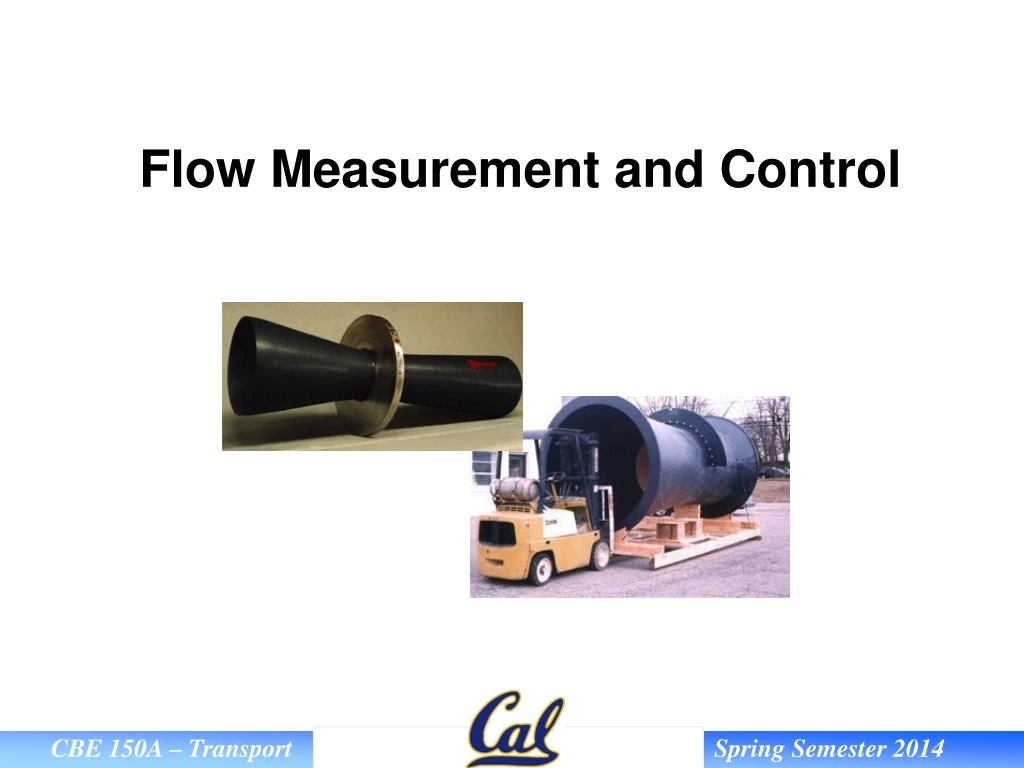
Explore the benefits and limitations of orifice meters compared to other flow measurement devices like venturi meters. Learn about the equation, pressure loss, and ASME design standards. Dive into other flow measurement techniques like rotameters, turbine meters, Coriolis meters, and pneumatic control valves.

E N D
Orifice Meter The orifice meter consists of an accurately machined and drilled plate concentrically mounted between two flanges. The position of the pressure taps is somewhat arbitrary.
Orifice Meter The orifice meter has several practical advantages when compared to venturi meters. • Lower cost • Smaller physical size • Flexibility to change throat to pipe diameter ratio to measure a larger range of flow rates Disadvantage: • Large power consumption in the form of irrecoverable pressure loss
Orifice Meter The development of the orifice meter equation is similar to that of the venturi meter and gives: where: • = ratio of orifice diameter to pipe diameter ≈ 0.5 usually S0 = cross sectional area of orifice V = bulk velocity through the orifice C0 = orifice coefficient ≈ 0.61 for Re > 30,000 –
There is a large pressure drop much of which is not recoverable. This can be a severe limitation when considering use of an orifice meter.
Rotameters Rotameters fall into the category of flow measurement devices called variable area meters. These devices have nearly constant pressure and depend on changing cross sectional area to indicate flow rate. Rotameters are extremely simple, robust devices that can measure flow rates of both liquids and gasses. Fluid flows up through the tapered tube and suspends a ‘float’ in the column of fluid. The position of the float indicates the flow rate on a marked scale.
Rotameters Three types of forces must be accounted for when analyzing rotameter performance: Buoyancy • Flow • Gravity • Buoyancy Gravity For our analysis neglect drag effect Flow
Rotameter CR must be determined experimentally. As Q increases the float rides higher.
Turbine Meter Measure by determining RPM of turbine (3) via sensor (6). Turbine meters are accurate but fragile.
Coriolis Meters When fluid is passed through a U-bend, it imposes a force on the tube wall perpendicular to the flow direction (Coriolis force). The deformation of the U-tube is proportional to the flow rate. Coriolis meters are expensive but highly accurate.
Orifice Meter Example An orifice meter reads a pressure drop of 20 psia, the process pipe is 2 inch Schedule 40 steel pipe and the orifice diameter is ½ inch. What is the flow rate of water in GPM through the line ??? The water temperature is 60 ºF.