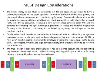
Design Considerations
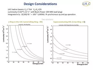
LHC hadron beams: E p =7 TeV E A = E e Z /A Luminosity O (10 33 ) cm -2 s -1 with Beam Power 100 MW (wall plug) Integrated e ± p : O(100) fb -1 ≈ 100 * L(HERA) synchronous ep and pp operation Two solutions

Design Considerations
E N D
Presentation Transcript
LHC hadron beams: Ep=7 TeV EA=EeZ/A Luminosity O (1033) cm-2s-1 withBeam Power 100 MW (wall plug) Integrated e±p : O(100) fb-1 ≈ 100 * L(HERA) synchronous ep and pp operation Two solutions e Ring in the LHC tunnel (Ring-Ring - RR) Superconducting ERL (Linac-Ring -LR) Design Considerations
New Physics Physics eQ states GUT (δαs=0.1%) Excited fermions Hot/cold spots Single top Higgs PDFs Multi-Jets DVCS Unintegrated partons Saturation Vector Mesons IP - graviton Odderons NC couplings sin2Θ Beauty Charm Partons in nuclei Shadowing …. Large x Physics and Range High precision partons in plateau of the LHC Nuclear Structure & dynamics High Density Matter Q2 = 4momentum transfer2 x = Bjorkenx: fraction of p’s momentum
LHeC - Participating Institutes TOBB ETU KEK
Accelerator: Ring - Ring Workpackagesas formulated in 2008, now in the draft CDR Baseline Parameters and Installation Scenarios Lattice Design [Optics, Magnets, Bypasses] IR for high Luminosity and large Acceptance rf Design [Installation in bypasses, Crabs?] Injector Complex [Sources, Injector] Injection and Dump Cryogenics – work in progress Beam-beam effects Impedance and Collective Effects Vacuum and Beam Pipe Integration into LHC e Beam Polarization Deuteron and Ion Beams LHeC Ring Dipole Magnet .12-.8T 1.3kA 0.8MW 5.3m long (35 cm)2 slim + light(er) 3080 magnets Prototypes: BINP-CERN
Magnets Injector to Ring – similarto Linac design [R+D] Novosibirsk dipole prototype measured field reproducible to the required 2 10-4 CERN prototype under test 3080 dipoles 336+148 F+D
Bypassing ATLAS For the CDR the bypass concepts were decided to be confined to ATLAS and CMS
Ring: Dipole + QuadrupoleMagnets BINP & CERN prototypes 5m long (35 cm)2 slim + light for installation 736 magnets 1.2 m long
LINAC - Ring Workpackagesas formulated in 2008, now in the draft CDR Baseline Parameters [Designs, Real photon option, ERL] Sources [Positrons, Polarisation] Rf Design Injection and Dump Beam-beam effects Lattice/Optics and Impedance Vacuum, Beam Pipe Integration and Layout Interaction Region Magnets Cryogenics IP2 1056 cavities 66 cryo modules per linac 721 MHz, 19 MV/m CW Similar to SPL, ESS, XFEL, ILC, eRHIC, Jlab 21 MW rf Cryo 29 MW for 37W/m heat load Magnets in the 2 * 3 arcs: 600 - 4m long dipoles per arc 240 - 1.2m long quadrupoles per arc Linac (racetrack) inside the LHC for access at CERN Territory U=U(LHC)/3=9km
60 GeV Energy Recovery Linac CERN 1 CERN 2 BNL Jlab Two 10 GeV energy recovery Linacs, 3 returns, 720 MHz cavities
CDR draft LINAC 60 GeV ERL
Design Parameters LHC “ultimate” pbeam used *) : 1.7 probably conservative Design also for D and A (LeN = 1031 cm-2s-1) RR= Ring – Ring LR =Linac –Ring Parameters from Draft CDR Ring:with1o as baseline : L/2 Linac: clearing gap: L*2/3 *) pulsed, but high energy ERL not impossible
LHeC Tentative Time Schedule LS3 --- HL LHC