Design Considerations for Water Intake Structures
180 likes | 246 Vues
Learn about key design considerations and calculations for water intake structures, including factor of safety, velocity, screening types, and screen design. Understand the importance of sufficient self-weight and velocity in intake design.

Design Considerations for Water Intake Structures
E N D
Presentation Transcript
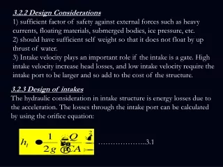
3.2.2 Design Considerations 1) sufficient factor of safety against external forces such as heavy currents, floating materials, submerged bodies, ice pressure, etc. 2) should have sufficient self weight so that it does not float by up thrust of water. 3) Intake velocity plays an important role if the intake is a gate. High intake velocity increase head losses, and low intake velocity require the intake port to be larger and so add to the cost of the structure. 3.2.3 Design of intakes The hydraulic consideration in intake structure is energy losses due to the acceleration. The losses through the intake port can be calculated by using the orifice equation: ………………..3.1
where, h = head loss, mQ = discharge, m3/sC = coefficient of discharge (0.6-0.9)A = effective submerged open area, m2
3.3 Screening A screen is a device with openings for removing bigger suspended or floating matter in water which would otherwise damage equipment or interfere with satisfactory operation of treatment units. 3.3.1 Types of Screens Coarse Screens: Coarse screens also called racks, are usually bar screens, composed of vertical or inclined bars spaced at equal intervals across a channel through which raw water flows. Clear space between bars ranges from 20 to 50 mm. Bar screens are usually hand cleaned and sometimes provided with mechanical devices. These cleaning devices are rakes which periodically sweep the entire screen removing the solids for further processing or disposal. Hand cleaned racks are set usually at an angle of 45° to the horizontal to increase the effective cleaning surface and also facilitate the raking operations. Mechanical cleaned racks are generally erected almost vertically. The angle of inclination of rack with horizontal is between 30o and 60o.
Fine screen: Fine screens have openings of approximately 6 mm are used to remove smaller objects that may damage pumps or other equipment such as leaves, twigs and fish a. They may be located either at the intake structure or at the raw water pump station. Figure 3.5 shows two types of screen. Coarse screen
Manual Bar Screen Mechanical Bar Screen
3.3.2 Design of screen The design velocity should be such as to permit 100% removal of material of certain size without undue depositions. Velocities of 0.6 to 1.2 m/s through the open area for the peak flows have been used satisfactorily. Further, the velocity at low flows in the approach channel should not be less than 0.3 m/s to avoid deposition of solids. Head loss varies with the quantity and nature of screenings allowed to accumulate between cleanings. The head loss created by a clean screen may be calculated by considering the flow and the effective areas of screen openings, the latter being the sum of the vertical projections of the openings. The head loss through a vertical bar screens is calculated from the following formula:
………….3.2 where, h = head loss in m = velocity through bar opening in m/s = approach velocity in m/s Another formula often used to determine the head loss through a bar rack is Kirschmer's equation: h = b (W/b)4/3 (v2/2g) sin q ……………..3.3
where h = head loss, m b = bar shape factor (2.42 for sharp edge rectangular bar, 1.83 for rectangular bar with semicircle upstream, 1.79 for circular bar and 1.67 for rectangular bar with both u/s and d/s face as semicircular). W = Width of, m b = Clear spacing between bars, m v = Approach velocity, m/s q = angle of inclination of rack with horizontal
Note: The head loss through screen can be calculated either by above equations or by orifice eq.(3.1). Orifice formula when the screen is located at the pumping station. Design example A mechanical bar screen is to be used in an approach channel with a maximum velocity of 1 m/s. The bars are 15mm thick, and the opening are 25mm wide. Determine the velocity between bars and the head losses. Solution
Example: A bar screen measuring 2 m by 5 m of surface flow area is used to protect the pump in a shoreline intake of a water treatment plant. The plant is drawing raw water from the river at a rate of 8 m3/sec. The bar width is 20 mm and the bar spacing is 70 mm. If the screen is 30% clogged, calculate the head loss throuogh the screen. Assume C=0.60.