Hardware status GOLD
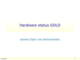
Hardware status GOLD. Generic Opto Link Demonstrator Assess the use of optical backplane connectivity for use on L1Calo. Gold floor plan. Z3. Opto. ATCA 8 processors 12 * SNAP12 receiver Fanout 6.5Gb/s SystemACE config Control/Merger SFP opto. Z2. Z1. GOLD.

Hardware status GOLD
E N D
Presentation Transcript
Hardware status GOLD Generic Opto Link Demonstrator Assess the use of optical backplane connectivity for use on L1Calo
Gold floor plan • Z3 • Opto • ATCA • 8 processors • 12 * SNAP12 receiver • Fanout 6.5Gb/s • SystemACEconfig • Control/Merger • SFP opto • Z2 • Z1
GOLD • Data concentrator scheme : many in, few out • ATCA form factor • 8U x 280 mm • Standard Zone1 connectivity (2*-48V supply scheme) • Currently no plans for use of Zone2 electrical connectivity • Zone3 (RTMs) 6.5Gb/s optical links • 8 processor FPGAs, 1 control/merger FPGA XC6VLX240T/550T-FFG1759 (24/36 * GTX link) • Optical inputs from backplane via bare fibre ribbons, 144 fibres • 12 * SNAP12 optical receivers (standard pin-out, not Avago) • Electrical link fan-out (*2) with CML buffers (SY58011 or similar) • Fanout scheme not yet defined. • ‘Realistic’ scheme would require knowledge of algorithms • Consider daughter connectors for half of the high speed links • AMC daughters not useful due to lack of optical connectivity • Use FMC daughters carrying SNAP12 modules and fanout chips • In case of problems the daughters could be re-designed for Avago transceivers • 2 GTX outputs per processor into merger FPGA • 1*SNAP12 out from control/merger FPGA • Couple of SFP links for control purposes (incl. serialised VME) • Clock recovery, jitter cleaner and clock fanout as on BLT • Parallel connectivity (up to 1Gb/s) via differential lanes only • 20 lanes to/from control/merger • Two blocks of 4 FPGAs linked locally ~ 120 lanes to each neighbour • Configuration via SystemACE (CompactFlash)
Optical backplane connectors • Available from a couple of manufacturers • Individual or 4-connector housings available • MT connectors for 12-36 fibres each, dependent on manufacturer (proprietary) • MT-to-MTP cable assemblies available from manufacturer only • expensive • MTP/MPO connectors for 12-72 fibres in single-connector housing • Takes more space than proprietary approach • 12-fibre ribbon will yield insufficient connection density on ATCA RTM boards • 24-fibre ribbons starting to become popular • Have a local supplier for custom made MTP 24-fibre ribbons and fanout cords (from January?) • Decide on baseline design very soon and order components • Opto/PCB purely mechanical interface only, allow for change of concept later
GOLD status / outlook • Components have been identified, including optical backplane connectors • Floor planning under way • Schematic capture started • Design along the lines of Xilinx ML605 (V6 specific) and BLT • Build module according to ATCA standard and with baseline backplane opto connector • Should provide input to L1Calo prototyping • Reconsider module size and optical interface upon transition from demonstrator to prototyping phase.