MICE Tracker Readout Update
210 likes | 359 Vues
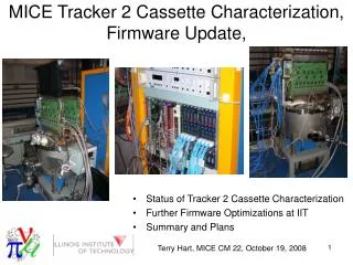
MICE Tracker Readout Update. Introduction/Overview TriP-t hardware tests AFE IIt firmware development VLSB firmware development Hardware progress Summary. Terry Hart, MICE CM 18, June 13, 2007. MICE Tracker Acronyms. AFE IIt – Analog Front End, Version II, with time

MICE Tracker Readout Update
E N D
Presentation Transcript
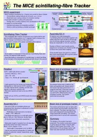
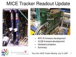
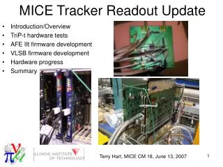
MICE Tracker Readout Update • Introduction/Overview • TriP-t hardware tests • AFE IIt firmware development • VLSB firmware development • Hardware progress • Summary Terry Hart, MICE CM 18, June 13, 2007
MICE Tracker Acronyms • AFE IIt – Analog Front End, Version II, with time • VLSB – VME LVDS Serdes Buffer • Versa Module Eurocard • Low Voltage Differential Signalling • Serialing/Deserializing • FPGA – Field Programmable Gate Array • TriP-t – Trigger with Pipeline with time • VLPC – Visible Light Photon Counter Terry Hart, MICE CM 18, June 13, 2007
Tracker Data Readout Basics Memory Bank X 4 … 1/4 of VLSB 1/4 of AFE-IIt DFPGA X 4 … AFPGA AFPGA X 4 … X 4 … ADC ADC ADC ADC Trigger and Pipeline chips - Sends bitmaps to DFPGA - Stores raw data in pipeline until receipt of MICE event trigger TriP-t TriP-t TriP-t TriP-t X 4 … Data from VLPCs
Tracker Data Readout Basics Memory Bank X 4 … 1/4 of VLSB 1/4 of AFE-IIt DFPGA X 4 … AFPGA AFPGA Analog FPGA Controls operation of TriP-t’s and ADCs. X 4 … X 4 … ADC ADC ADC ADC Trigger and Pipeline chips - Sends bitmaps to DFPGA - Stores raw data in pipeline until receipt of MICE event trigger TriP-t TriP-t TriP-t TriP-t X 4 … Event Trigger (L1ACCEPT) Data from VLPCs
Tracker Data Readout Basics Memory Bank X 4 … 1/4 of VLSB 1/4 of AFE-IIt DFPGA X 4 … AFPGA AFPGA Analog FPGA Controls operation of TriP-t’s and ADCs. X 4 … Analog to Digital Converters Digitizes raw charge and time data X 4 … ADC ADC ADC ADC Trigger and Pipeline chips - Sends bitmaps to DFPGA - Stores raw data in pipeline until receipt of MICE event trigger TriP-t TriP-t TriP-t TriP-t X 4 … Event Trigger (L1ACCEPT) Data from VLPCs
Tracker Data Readout Basics Memory Bank X 4 … 1/4 of VLSB 1/4 of AFE-IIt Digital FPGA Sets data protocol for - Bitmaps to AFPGA - Data from AFPGA DFPGA X 4 … AFPGA AFPGA Analog FPGA Controls operation of TriP-t’s and ADCs. X 4 … Analog to Digital Converters Digitizes raw charge and time data X 4 … ADC ADC ADC ADC Trigger and Pipeline chips - Sends bitmaps to DFPGA - Stores raw data in pipeline until receipt of MICE event trigger TriP-t TriP-t TriP-t TriP-t X 4 … Event Trigger (L1ACCEPT) Data from VLPCs
Tracker Data Readout Basics Formatted Data to VLSB Memory Banks Memory Bank X 4 … 1/4 of VLSB 1/4 of AFE-IIt Digital FPGA Sets data protocol for - Bitmaps to AFPGA - Data from AFPGA DFPGA X 4 … AFPGA AFPGA Analog FPGA Controls TriP-t and ADC operation. X 4 … Analog to Digital Converters Digitizes raw charge and time data X 4 … ADC ADC ADC ADC Trigger and Pipeline chips - Sends bitmaps to DFPGA - Stores raw data in pipeline until receipt of MICE event trigger TriP-t TriP-t TriP-t TriP-t X 4 … Event Trigger (L1ACCEPT) Data from VLPCs
AFE IIt/TriP-t Basics • For MICE, average time between triggers ~ 1700 ns, but can be as short as 628 ns. (ISIS beam structure and MICE DAQ constraints) • TriP-t chips • Pipeline stores analog charge and time data. • L1ACCEPT event trigger takes time (~ 1000 ns) to be formed. • Time to digitize analog data ~ 1500 – 2000 ns. • Upon L1ACCEPT trigger, data is taken from pipeline and either • Digitized if 4-level buffer is empty or • Placed in 4-level buffer if digitization of previous event not yet done Terry Hart, MICE CM 18, June 13, 2007
TriP-t Modifications for MICE D0 AFE IIt firmware doesn’t • Implement TriP-t 4-level analog buffer. • Run data pipeline while ADCs digitize data. Firmware modified to do these, but hardware tests needed to ensure that TriP-t chips operate as expected. Terry Hart, MICE CM 18, June 13, 2007
Hardware Tests of Increasing Fraction of Recorded Muons • Completed TriP-t test stand • DG2020 Signal Generator • 2 Tektronix P3420 Variable Level Pods • Test board containing TriP-t chip • Fed signals into TriP-t test board. First results: TriP-t seems to function with input zero suppression signal sequence . Next steps: - Check output signal integrity to see if input signals were digitized. - Check if buffering events works. [Reported at MICE Collaboration Meeting, Feb. 22, 2007]
Preamplifier Signals TriP-t Chip Signal Inputs Pipeline Control Signals Program Interface Signals
2.268 µs 1.620 µs 1.620 µs 1.620 µs • Charges injected at four 324 ns • intervals • Data placed in 4-level buffer • PR1 starts pipeline readout • Analog outputs from pipeline • are correct • Digitization times • - 4 channels => 2268 ns • - 3 channels => 1620 ns 2.268 µs 1.620 µs 1.620 µs 1.620 µs 1 15,16 31 1 15 31 15,16 31 1 16 31 • Channel Inputs • 4 channels in gate #1 (1,15,16,31) • 3 channels in gate #2 (1,15,31) • 3 channels in gate #3 (15,16,31) • 3 channels in gate #4 (1,16,31)
TriP-t Hardware Test Summary • Test stand has demonstrated that TriP-t can • Run pipeline while ADCs digitize raw data • Store data in 4-level analog pipeline for later readout Terry Hart, MICE CM 18, June 13, 2007
AFE IIt Firmware Modifications Memory Bank Modifications needed for data buffering • Shorten time to digitize data • Zero suppression • End digitization series after last channel above threshold These are done. • Protocol for data transfers between DFPGA and AFPGA • Bitmaps from DFPGA to AFPGA • Digitized data from AFPGA to DFPGA This is nearly done. • Buffer triggers in DFPGA FIFO This is nearly done. DFPGA AFPGA AFPGA ADC ADC ADC ADC TriP-t TriP-t TriP-t TriP-t Data from VLPCs
Immediate AFE IIt Firmware Tasks • Synthesize AFGPA and DFPGA firmware modifications. • FNAL concentrating of AFPGA • RAL concentrating on DFPGA • Test operation of entire board. • Check that modified firmware is compatible with existing firmware. Terry Hart, MICE CM 18, June 13, 2007
VLSB Firmware • VLSB = VME LVDS Serdes Buffer • Tracker data storage modules • Used for KEK test beam • Used by D0 for diagnostics • Modifications for MICE • Event counter during spill Should be straightforward • Fast clear of VLSB memory Should be straightforward • Overwrite memory addresses when there’s null data so that data are stored in continuous memory blocks. Initial code formulated to be tested • Enable Direct Memory Access block transfers Done VLSB memory banks storing charge and time data DFPGA directs DFPGA and AFPGA data flow AFPGA controls ADC and TriP-t operation Done Terry Hart, MICE CM 18, June 13, 2007
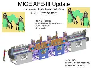
Hardware Updates • VLSB Boards • 9 boards are built (to be spares), • 15 more to be made. • Need 8 new production VLSB boards by August 1. • AFE IIt boards/Cryostat • Data taken for 2 of 4 production cryostats • More details in Alan’s talk Terry Hart, MICE CM 18, June 13, 2007
Fallback for Tracker Readout • DAQ goal: Keep up with 600 kHz trigger rate. • At start of MICE in Aug./Sept., original firmware is sufficient for initial low data rate. • With TriP-t zero-suppression, tracker can keep up with almost 300 kHz now. • Late June/early July: target time for firmware capable of keeping pace with 600 kHz trigger rate. Terry Hart, MICE CM 18, June 13, 2007
600 480 360 240 120 0 1000 2000 3000 4000 4-level Buffering 3-level Buffering 2-level Buffering 1-level Buffering No Buffering Where we are. Recordable Muon Rate (kHz) Digitization Time (ns)
Jan Feb Mar Apr May Jun Jul Aug Sep Oct Nov Dec TriP-t/ADC Control Firmware Hardware tests DFPGA/AFPGA I/O Bus Board test at 53.104 MHz Board test at 55 MHz Simulations at different frequencies Data transfer protocol AFPGA Firmware Write firmware controlling bitmap transfers Test pipeline/buffer operation Test mode development DFPGA Firmware Make 4-level trigger buffer Data format VLSB Firmware Event aggregation (VLSB) Data block transfer Fast clear of memory banks Suppress writing zeros to memory VLSB Board Manufacture (13 boards) AFE IIt Board Preparation Repairs for MICE Firmware and hardware modifications Board characterization in cryostats Ship cryos/boards to RAL Done Done Done Conservative simulations indicate this is marginal Conservative simulations this is marginal Done Done Standalone routine written Feedback loop testing previous version Done Low to middle priority Done Should be quick Initial code written, needs to be tested Follow up on existing MOU Ongoing Ongoing Ongoing
Summary • TriP-t operation tested and verified to work • AFE IIt firmware development to enable trigger buffering almost done. • VLSB firmware development almost done. Terry Hart, MICE CM 18, June 13, 2007