The MICE scintillating-fibre Tracker
10 likes | 177 Vues
Coupling Coils 1&2. Spectrometer solenoid 1. Matching coils 1&2. Matching coils 1&2. Spectrometer solenoid 2. Focus coils 1. Focus coils 2. Focus coils 3. m. Beam PID TOF 0 Cherenkov TOF 1. RF cavities 1. RF cavities 2. Downstream TOF 2 particle ID: KL and SW

The MICE scintillating-fibre Tracker
E N D
Presentation Transcript
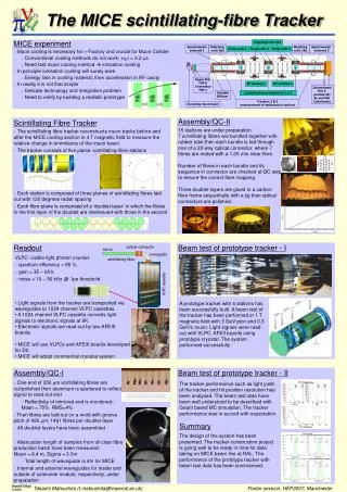
Coupling Coils 1&2 Spectrometer solenoid 1 Matching coils 1&2 Matching coils 1&2 Spectrometer solenoid 2 Focus coils 1 Focus coils 2 Focus coils 3 m Beam PID TOF 0 Cherenkov TOF 1 RF cavities 1 RF cavities 2 Downstream TOF 2 particle ID: KL and SW Calorimeter VariableDiffuser Liquid Hydrogen absorbers 1,2,3 Trackers 1 & 2 measurement of emittance in and out Incoming muon beam optical connector mirror waveguide scintillating fibre VLPC cassette The MICE scintillating-fibre Tracker MICE experiment • Muon cooling is necessary for n-Factory and crucial for Muon Collider • Conventional cooling methods do not work; t(m) = 2.2 ms • Need fast muon cooling method ionisation cooling • In principle ionisation cooling will surely work • Energy loss in cooling material, then acceleration in RF cavity • In reality it is not that simple • Delicate technology and integration problem • Need to verify by building a realistic prototype Assembly/QC-II Scintillating Fibre Tracker 15 stations are under preparation. 7 scintillating fibres are bundled together with rubber tube then each bundle is fed through one of a 22-way optical connector, where 7 fibres are mated with a 1.05 mm clear-fibre. Number of fibres in each bundle and its sequence in connector are checked at QC step to ensure the correct fibre mapping. Three doublet-layers are glued to a carbon fibre frame sequentially with a jig then optical connectors are polished. • The scintillating fibre tracker reconstructs muon tracks before and after the MICE cooling section in 4 T magnetic field to measure the relative change in emmitance of the muon beam • The tracker consists of five planar scintillating-fibre stations • Each station is composed of three planes of scintillating fibres laid out with 120 degrees radial spacing • Each fibre plane is comprised of a ‘doublet-layer’ in which the fibres in the first layer of the doublet are interleaved with those in the second Readout Beam test of prototype tracker - I • VLPC: visible light photon counter • quantum efficiency = 85 % • gain = 35 – 60 k • noise = 10 – 50 kHz @ 1pe threshold • Light signals from the tracker are transported via waveguides to 1024 channel VLPC cassettes. • A 1024 channel VLPC cassette converts light signals to electronic signals at 9K. • Electronic signals are read out by two AFEIIt boards. • MICE will use VLPCs and AFEIIt boards developed for D0. • MICE will adopt commercial cryostat system A prototype tracker with 4 stations has been successfully built. A beam test of the tracker has been performed in 1 T magnetic field with 3 GeV pion and 0.3 GeV/c muon. Light signals were read-out with VLPC, AFEII boards using prototype cryostat. The system performed successfully. Assembly/QC-I Beam test of prototype tracker - II • One end of 350 mm scintillating fibres are cut/polished then aluminum is sputtered to reflect signal to read-out end • Reflectivity of mirrored end is monitored;Mean = 75% RMS=4% • Then fibres are laid-out on a mold with groove pitch of 426 mm; 1491 fibres per doublet-layer • 48 doublet-layers have been assembled • Attenuation length of samples from all clear fibre production batch have been measured;Mean = 8.4 m, Sigma = 0.5m • Total length of waveguide is 4m for MICE • Internal and external waveguides for inside and outside of solenoide module, respectively, under preparation The tracker performance such as light yield of the tracker and hit position resolution has been analysed. The beam test data have been well understood to be described with Geant based MC simulation. The tracker performance was in accord with expectation. Summary The design of the system has been presented. The tracker-construction project is going well to be ready in time for data taking on MICE beam line at RAL. The performance of the prototype tracker with beam test data has been summarised. Takashi Matsushita (t.matsushita@imperial.ac.uk) Poster session, HEP2007, Manchester