Download
1 / 9
90 likes | 227 Vues
Dead Time and Muon Detection Studies for the MICE Tracker. Tracker Data Readout Basics Progress in Increasing Fraction of Muons Tracker Can Record Ideas for Further Improvement Plans and Outlook. Terry Hart, Illinois Institute of Technology, NFMCC Friday Meeting. Tracker Data Readout Basics.

E N D
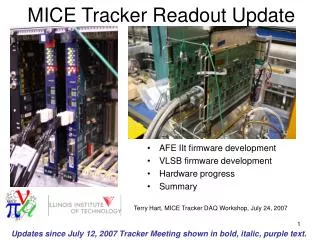
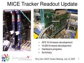
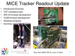
Dead Time and Muon Detection Studies for the MICE Tracker • Tracker Data Readout Basics • Progress in Increasing Fraction of Muons Tracker Can Record • Ideas for Further Improvement • Plans and Outlook Terry Hart, Illinois Institute of Technology, NFMCC Friday Meeting
Tracker Data Readout Basics 16 Analog Front End II t (AFE-IIt) boards • Inputs: Analog charge signals from 512 channels • Outputs: Digital hit pattern, charge amplitudes, time amplitudes • Each board contains sixteen 32-channel Trigger and Pipeline (TriP-t) chips. • The data from all 16 chips are processed in parallel • Within each chip the 32 channels are processed in series. DFPGA X 4 … AFPGA AFPGA X 4 … X 4 … ADC ADC ADC ADC TriP-t TriP-t TriP-t TriP-t X 4 … Data from VLPCs 1/4 of AFE-IIt board Terry Hart, Illinois Institute of Technology, NFMCC Friday Meeting
Muon Detection • Digitization of analog charge and time data limits the fraction of muons the tracker will record. • Primary efforts in tracker firmware development have been to reduce time to digitize 32 channels of each TriP-t chip through zero suppression. • Have performed a detailed study of how many muons the tracker can record. Terry Hart, Illinois Institute of Technology, NFMCC Friday Meeting
Muon Recording With D0 configuration and 600 kHz muon rate, AFE-IIt boards can record about 136 kHz Increase number of recorded muons by • Decreasing digitization time • Zero suppression • Have TriP-t pipeline collect data during digitization • Remove unnecessary setup cycles • Implementing TriP-t buffer • Digitization time ≠ dead time. Terry Hart, Illinois Institute of Technology, NFMCC Friday Meeting
Reducing Digitization Time • Assumed muon rate is 600 kHz for average time between muons of 1667 ns. • Clock period taken as 18 ns • Assume 2 out of 32 channels of TriP-t have charge data above threshold • ~ 5724 ns: D0 implementation • ~ 5670 ns: Adjust for shorter ISIS bucket period • 4536 ns: TriP-t pipeline collect data during digitization • 2376 ns: Zero-suppress 30 of 32 TriP-t channels • 1836 ns: Reduce zero-suppression time from 2 to 1 cycle. • 1566 ns: Remove cycles from set-up processes. We are now starting to reduce the dead time so that it’s comparable to the average time between muons. Terry Hart, Illinois Institute of Technology, NFMCC Friday Meeting
Implementing Buffer • TriP-t chips have 4-level analog buffers which have not been implemented nor tested. • Using one level of buffer greatly increases fraction of muons recorded. Example: x x x 3 7 2 4 5 6 1 4 of 7 muons recorded No Buffer 1 3 4 7 x 3 7 2 4 5 6 1 6 of 7 muons recorded 1-level Buffer 1 2 3 4 5 7 Terry Hart, Illinois Institute of Technology, NFMCC Friday Meeting
Benefits of Adding Buffer and Reducing Digitization time • Clock period taken as 18 ns • Assume 2 out of 32 channels of TriP-t have charge data above threshold Fraction of Recorded Muons for 600 kHz No Buffering 1-level Buffer tdigi = 5670 ns 0.227 0.291 tdigi = 2376 ns 0.412 0.601 tdigi = 1836 ns0.476 0.699 tdigi = 1566 ns0.516 0.753 Terry Hart, Illinois Institute of Technology, NFMCC Friday Meeting
Suggested Strategy Benefits of implementing one level of buffer greater than reducing digitization time. Fraction of Recorded Muons for 600 kHz No Buffering 1-level Buffer tdigi = 5670 ns 0.227 0.291 tdigi = 2376 ns 0.412 0.601 tdigi = 1836 ns0.476 0.699 tdigi = 1566 ns0.516 0.753 Terry Hart, Illinois Institute of Technology, NFMCC Friday Meeting
Plans and Outlook • Continue firmware development to reduce digitization time and implement TriP-t buffer. • Test digitization, buffering, and firmware with TriP-t chips and AFE-IIt boards. • Write up MICE Note which includes derivations of fraction of detected muons. Terry Hart, Illinois Institute of Technology, NFMCC Friday Meeting