MICE Tracker
MICE Tracker. Outline. Tracker design 5 Station tracker 3 planes of scintillating fibre Readout with VLPCs Prototypes Quality Assurance Tracker construction Fibre Mirroring Doublet plane fabrication Waveguides VLPC Cassette Cryostats. A MICE Tracker. Tracker is in a 4T Solenoid.

MICE Tracker
E N D
Presentation Transcript
MICE Tracker M. Ellis - NFMCC - 31st January 2007
Outline • Tracker design • 5 Station tracker • 3 planes of scintillating fibre • Readout with VLPCs • Prototypes • Quality Assurance • Tracker construction • Fibre Mirroring • Doublet plane fabrication • Waveguides • VLPC Cassette Cryostats M. Ellis - NFMCC - 31st January 2007
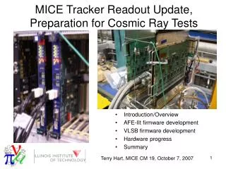
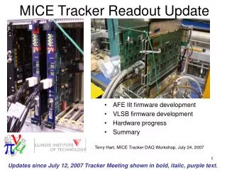
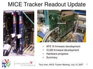
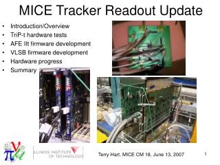
A MICE Tracker Tracker is in a 4T Solenoid A “Station” Carbon Fibre Support M. Ellis - NFMCC - 31st January 2007
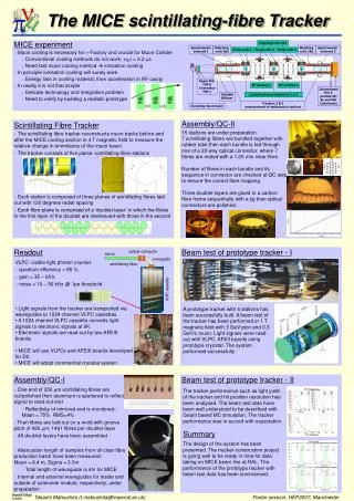
426 mm Fibre Plane Active Area Radius > 15cm • 350 mm scintillating fibres are arranged in two overlapping rows to form a sheet of fibre. • Active area has a diameter of 30 cm. • Small fibre minimises radiation length in direction of muon passage. M. Ellis - NFMCC - 31st January 2007
Readout • Position resolution required is of order 1mm, so no need to read out every single fibre. • Gang 7 neighbouring fibres together into one channel and the light is read out over clear fibre by Visible Light Photon Counters (VLPCs). M. Ellis - NFMCC - 31st January 2007
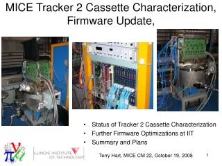
VLPCs • Visible Light Photon Counters – operate at 9 Kelvin. • Combine high QE with low noise and high rate capability. • D0 expertise is gradually being transferred to MICE. • Readout through AFEIIt boards (D0 upgrade) firmware modified for MICE (see T. Hart’s talk). M. Ellis - NFMCC - 31st January 2007
Prototypes • Several prototype trackers have been built to test the design and construction techniques. • First 3 station tracker was completed in October 2003 and tested in cosmic rays at Fermilab in 2003 and 2004. • An additional station was built to refined specifications with new connectors and tested in a beam (in a 1T solenoid) at KEK in October 2005. • Analysis of the data is ongoing, but an issue with the precision drilling of holes for the fibres was discovered and a 5th station is currently being completed and will be tested as proof of the final design, construction and quality assurance techniques before the final trackers for MICE are built. M. Ellis - NFMCC - 31st January 2007
Tests at FNAL and KEK M. Ellis - NFMCC - 31st January 2007
Towards the Final Trackers • Preliminary results from analysis of the KEK data show lower light yield from the 4th station than expected. • This has been traced back to an issue with the CNC drilling of the holes in the connectors. • Construction and testing of the 5th station should verify that this is now solved. • In addition, several tools and techniques have been developed to assist the people when building the tracking planes, in particular: • When bundling 7 fibres into a channel (detect and correct accidental swaps of fibre from one channel into another or incorrect number of fibres in a bundle). • When threading bundles into the station connectors, test to ensure that the channels have been inserted into the correct position. M. Ellis - NFMCC - 31st January 2007
QA for Bundling and Connectorisation Ensure each bundle has correct 7 fibres Ensure correct mapping from plane to connector M. Ellis - NFMCC - 31st January 2007
QA Software CCD images are analysed by software (Imperial College) The software notifies the operator if there is any failure or suspicious bundles. M. Ellis - NFMCC - 31st January 2007
Fibre Mirroring and Ribbons • All scintillating fibres have been mirrored. • A small fraction may need to be re-done. • Average reflectivity of the mirror is 75% (RMS 4%). • Ribbon production is well underway with over 28 complete (most of which are now in London). M. Ellis - NFMCC - 31st January 2007
Waveguides • Waveguides are currently being assembled in Japan. • Have had some issues with the fibre size and holes in the connectors. • Revised procedure has been devised to reduce risk of damage. External Waveguide Internal Waveguide Test cookie for fiber QA Test cookie D0 connector Bulkhead connectors Station connectors M. Ellis - NFMCC - 31st January 2007
Cryostats • A prototype two cassette cryostat has been built and operated successfully in the US and Japan. • Most of the parts for the four production cryostats have arrived and they are being assembled at Fermilab. • During this week the first production cryostat is being tested at Fermilab. • All four should be tested and ready to be delivered to RAL in the spring. • Prototype cryostat with one VLPC cassette will go to London to be used to readout the stations that are being assembled for the final trackers as part of the quality control process. M. Ellis - NFMCC - 31st January 2007
Station Production Status • Station 6: • View X + bundling/QA + connectorisation • View W + bundling/QA -- Connectorisation ETA: five stations – end of March M. Ellis - NFMCC - 31st January 2007
Coming months should see: • Complete analysis of KEK data • Commissioning of first MICE production cryostats. • Completion of system for characterising all VLPC cassettes used in MICE. • Preparation of a readout system based on the prototype cryostat to be used to readout Station 5 in a cosmic ray test and later used with a radioactive source for testing of all final stations. • Progress on MICE firmware for the AFEIIt boards. • Completion of waveguides. • Construction and testing of MICE tracker stations. M. Ellis - NFMCC - 31st January 2007