Download
1 / 27
280 likes | 476 Vues
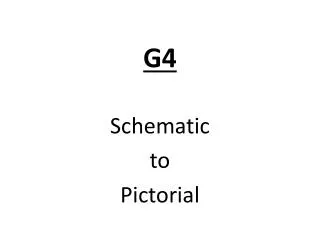
A6a to A6b Schematic Diagram to Pictorial Diagram. Turn to page A6a and A6b in the Student Handout Packet. If you have NOT viewed the power point presentation entitled ‘glow coil’, please do so BEFORE you continue on with this schematic to pictorial.

E N D
Turn to page A6a and A6b in the Student Handout Packet. If you have NOT viewed the power point presentation entitled ‘glow coil’, please do so BEFORE you continue on with this schematic to pictorial.
Follow the schematic to wire the pictorial. Please complete YOUR page A6b as you proceed through the following slides.
24v from the ‘P’ terminal goes to the ‘R’ terminal of the terminal strip, then to the thermostat and back from the thermostat to the ‘W’ terminal of the terminal strip. P C
C P Please mark the P and C terminals on the control transformer.
C P There is NO terminal strip so go directly to the thermostat.
C P
C P
C P
24v continues from the gas valve to the NO terminal of the Baso switch, which they are calling the ignitor relay (same thing). P C
C P
We are going to back up and start again at the ‘P’ terminal of the control transformer. We come out of the ‘P’ terminal and go to the ‘Pilot Pressure Switch.’ P C
C P
We come out of the pilot pressure switch and go to the ignition transformer primary. P C
C P
We come out of the primary of the ignition transformer and go to the NC terminal of the Baso switch. P C
C P
We come out of the C terminal of the Baso and go to the C terminal of the control transformer. P C
C P
Add two wires from the ignition transformer to the ignitor (glow coil). P C
C P
You have finished theheating low voltage circuits pictorialfollowing aschematic