Download
1 / 71
730 likes | 894 Vues
This guide walks you through analyzing and wiring a single phase fan motor circuit setup. You will learn about shaded pole motors, jumper configurations, and the switching actions for the fan limit and electronic air cleaner (EAC). By following the schematic one wire at a time, you'll successfully complete wiring for both the power and control circuits. This process will enhance your practical skills in handling electrical diagrams and ensure a comprehensive understanding of the system's operation.

E N D
Turn to page K3 in the Student Handout Packet Answer the following questions.
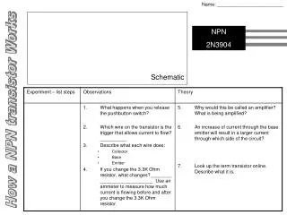
What type of single phase fan motor is used on this equipment?
You should notice there are no starting relays or capacitors. It can only be a Shaded Pole.
Does the fan and limit have a jumper? Refer back to K1 if you need help in answering this question.
This circuit is for heating and cooling. It also includes an electronic air cleaner (EAC).
Your answer should be: DPST. There are two inputs: one from L1 (H) and the other one from the NO contacts of the FL.
This EAC is deceiving because it appears as if there are two inputs. But a more educated analysis will indicate it is nothing more than a mirror image of a SPDT relay.
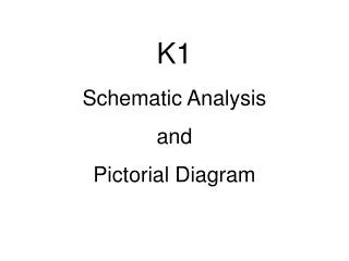
But is the EAC really a SPDT? Go to the PICTORIAL on page K3a and check it out.
When you look at the pictorial, you should determine that it is a DPST – 1NO, 1NC
The process will be to follow the schematic one wire at a time from one component to another component until we are finished.
The slides that follow will show the wire in RED on the schematic that is going to be wired on the pictorial. Then the pictorial slide will show that wire being ‘installed.’ That is the wire you are to place on your pictorial. Keep advancing through the slides until you are finished with the pictorial.
Turn to page K3a and you will see, at the top of the page, that this page is to be used to wire the POWER circuit. Turn to page K3b and you will see, at the top of the page, that this page is to be used to wire the CONTROL circuit.
So let’s begin with K3a and the POWER circuit first. This will be a very difficult schematic to follow because it will seem as if the wires go everywhere. Sometimes it is best to check off the wires as you ‘wire’ them.
Move onto K3b and the CONTROL circuit. This will not be as difficult as the POWER circuit.